The Idea
The idea to build this rover came out of the need for a project for my ECE362 class at Purdue University.
In this class we learned how to program and apply microcontrollers in C and assembly.
We used the stm32f0discovery board which has an stm32f051r8 microcontroller.
I had previously built a small rover two summers ago that I could control over wifi with a Raspberry Pi.
It used two l298n motor drivers to control four motors with roller wheels arranged in a square. This allowed the
rover to instantly go in any cardinal direction and rotate on a point. I knew that this project could be
converted to use the stm32 microcontroller and would be a great project for this assignment, so I pitched it to
my team. Together we decided to go ahead and do it.
We decided on the following criteria for the project:
- two way radio to control the car and display data on the controller
- analog input
- pwm output to motor drivers
- a screen on the controller to display data
- at least 2 input buttons on the controller to rotate the rover
- an imu on the car to measure rotation and acceleration
- (if time) some kind of camera to collect visual data
At a minimum the car should be able to move and be controlled via radio and the imu data should be sent
back to the controller and be displayed on the screen.
The Controller
I primarily worked on the controller and early on I made the decision to write the program in
Rust. I made the decision to use this language because I had been
looking for project to learn Rust with, and I had heard from a friend that stm32 microcontrollers could be
programed with it. It took me a weekend to get an environment setup to flash the microcontroller and another
week to get used to programming in Rust.
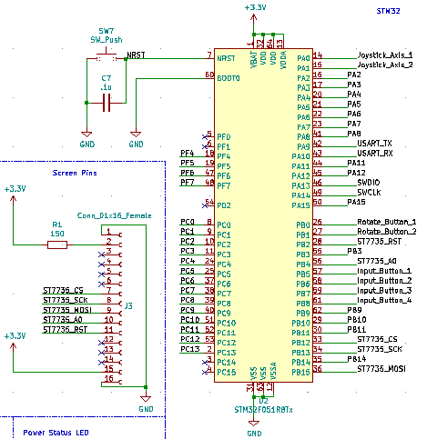
I started the controller schematic with the stm32f051r8 and labeling the pins that I was planning on using for the analog stick, buttons, Xbee, and screen.
The stm32f056r8 pin labels and the pinout for the st7735 screen.
 |
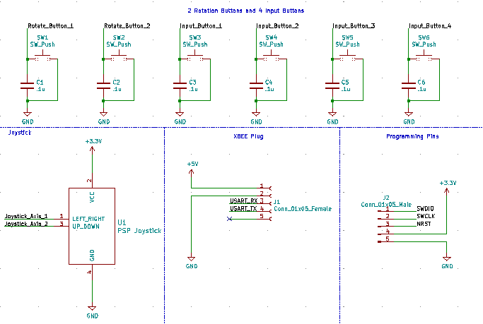
Next I added buttons with debouncing capacitors, a header for the Xbee adapter, a PSP analog stick,
and programming pins for the microcontroller.
Buttons, analog stick, Xbee adapter header, and programming pins.
 |
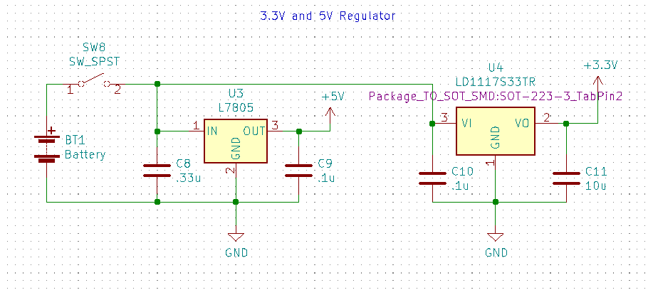
To power the controller I decided to use a 9 volt battery and regulate it to 5V and 3.3V.
9 volt battery with l7805 and ld1117s33 regulators and decoupling capacitors.
 |
Lastly I added a status LED and decoupling capacitors for the microcontroller to finish the schematic.
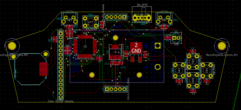
After completing the schematic I added footprints for all of the components, arranged them on a pcb, routed
the traces, added fill areas, and added cut lines.
The pcb for the controller.
 |
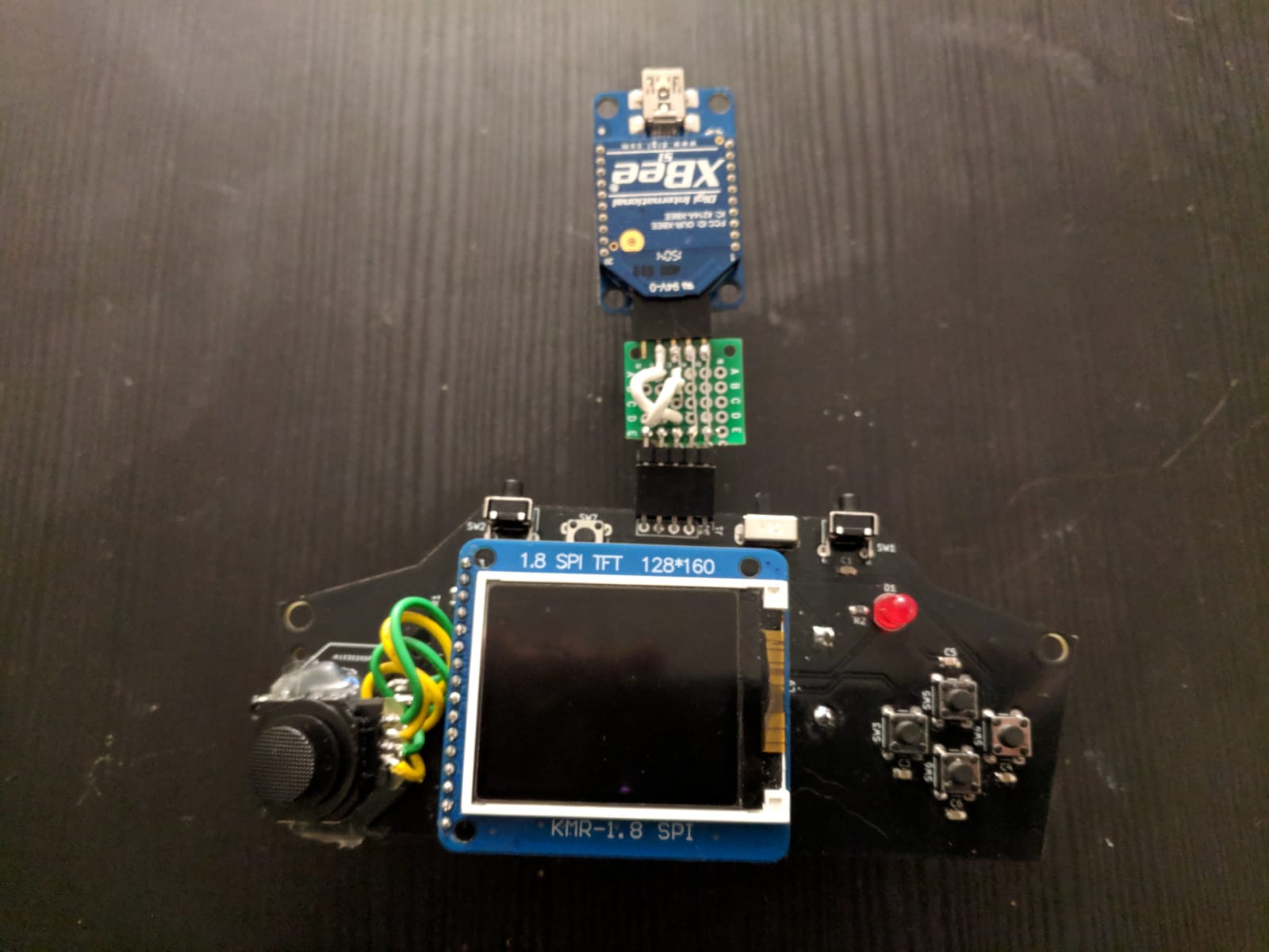
We ordered the pcbs and components and soldered the components on. Below is the end result. There were two big errors with this board. I forgot to cross connect the tx and rx pins on the microcontroller and the Xbee
adapter. I was also unable to surface mount solder the PSP analog stick so I had to improvise and hot glue it on.
The completed controller.
 |
The Car
I did not directly program the car, but the program was written in C by my teammates. The program sends sensory data back to the controller from the imu and infrared camera to be displayed on the screen and it receives
movement data from the controller that is written to the motor drivers.
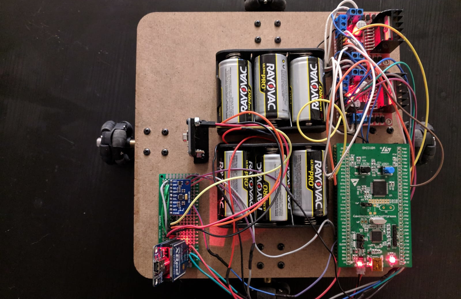
We tried to create a pcb for the motor drivers, but we made mistakes when designing it that rendered the pcb unusable. Because of this mistake, we put the stm32f0discovery board on protoboard and wired it to two l298n motor drivers and another protoboard containing the imu, Xbee, and the headers for the amg8833 infrared camera.
We also used six C batteries in two battery packs as a power supply and we used a 5V regulator to power the stm32f0discovery board.
Top view of the rover.
 |
All of the rover electronics were mounted on a wooden plate made of laser cut 1/8 inch mdf. Motors were mounted on the bottom of the plate and fitted with wheels with rollers.
The Result
The rover ended up working very well. It is quite responsive and can even move diagonally. We currently have
the rover transmitting data back to the controller about once per second. Below is a video demonstration.
Conclusion
We were really happy with the result of this project. I have plans to improve it over the summer and convert all
of the code to Rust. I plan on opensourcing the rover design and code once I organize the project and will post an update here when this happens.
I had trouble finding good resources for getting started with embedded Rust. My hope for the future of this project is to create a good starting point for embedded Rust programming, so that others will have an easier time learning it than I did.
Stay tuned for updates!