Prerequisite Guides
Supplemental Guides
You Will Need
| ESP8266 NodeMCU |
| MicroUSB Cable |
| Computer running Windows, Linux, or MacOSX |
| Breadboard |
| LED |
| 46Ω - 100Ω Resistor |
| 10k Potentiometer |
| Jumper Wires |
Setup
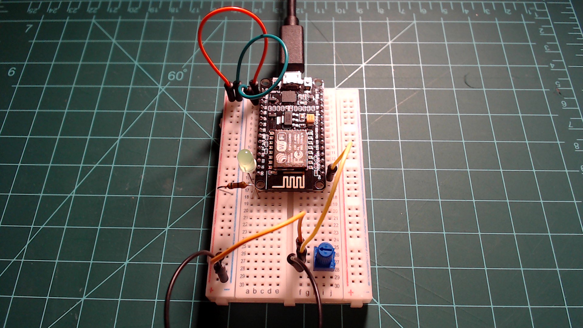
Connect one of the 3V3 pins on the NodeMCU to a breadboard rail and one of the GND pins on the NodeMCU to another rail. Connect an LED to GPIO5 in series with the resistor going to the GND rail. Lastly, place the 10k potentiometer on the breadboard and connect it’s middle pin to the pin on the NodeMCU labeled as “A0” this is pin ADC0. Then connect one of the outer pins to the 3.3V rail on the breadboard and the other outer pin to the GND rail.
An LED connected to GPIO5 and a potentiometer connected to ADC0.
 |
PWM (Pulse Width Modulation)
PWM is a unique type of digital signal that has the effect of reducing the average power delivered. Previously, we have been setting pins to full power (HIGH) or no power (LOW). PWM allows us to set the average power to somewhere in between. This is done through the use of precisely timed pulses of full power to the pin.
Duty Cycle
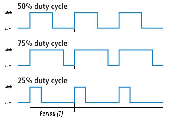
“Duty cycle” is a term referring to the the percentage of time in a signal’s period in which it is “active” or HIGH. In our case, “active” refers to being powered at 3.3V. For example, if during a period a pin is powered to 3.3V half the time and 0V the other half, then the pin has a 50% duty cycle. Below are examples of different duty cycles.
Examples of signals with different duty cycles.[1]
 |
Frequency
Frequency in relation to PWM refers to the length of the period that the duty cycle applies to. Frequency refers to “cycles per second”, and period is the amount of time per cycle. These to values have a relationship of T=1/f where f is the frequency and T is the length of time for the period. For example, if the frequency is set to 1 Hz (one cycle per second) then the period is one second. If the frequency is set to 2 Hz, then the period is 500 milliseconds. If the frequency is set to the maximum PWM frequency for the ESP8266, which is 1000 Hz, then the period is 1 millisecond.
Initialization
The code below is an example initialization of a PWM pin. It sets GPIO5 to a PWM output with its frequency set to 1000 Hz and its duty cycle set to 512. Why is the duty cycle set to 512 when we have been previously referring to it as a percentage? The duty cycle value has 10 bits of resolution which means it can be set to any number between 0 and 1023. 512 is roughly halfway between 0 and 1023 so we effectively set the duty cycle to 50%. With an LED connected to GPIO5 this code would have the effect of providing half power to the LED over time.
pwm_led = PWM(Pin(5), freq=1000, duty=512)
Each of the parameters is itemized below for clarity:
- The first parameter is a desired Pin object to make into a PWM output.
- The second parameter is the frequency in Hertz. This value can range between 1 Hz and 1000 Hz.
- The third parameter is the duty cycle. This is value ranging from 0 to 1023 with 0 being a 0% duty cycle and 1023 being a 100% duty cycle.
Testing PWM
Plug your NodeMCU into your computer, open Thonny, and acquire a REPL by pressing the stop button at the top of the window. Enter the following code into the Thonny editor and save it to your device as “main.py” then press the restart button on your device. This code initializes GPIO5 as a PWM output.
from machine import Pin, PWM

pwm_led = PWM(Pin(5))
Notice that we don’t need to specify values for frequency and duty cycle. By default frequency is set to 500 and the duty cycle is set to 0. To check the current frequency and duty cycle on a PWM pin you can call the freq and duty functions on the pin with no parameters.
pwm_led.freq() check the frequency value of the PWM pin.pwm_led.duty() check the duty cycle value of the PWM pin.
Below are some examples that help to illustrate PWM. I encourage you to play around with other values on your own until you thoroughly understand what is going on.
In the example below, the period is one second and the duty cycle is 767/1023 which is roughly 75%. This means that in any period the LED is on for 750 milliseconds and off for 250 milliseconds.
pwm_led.freq(1)
pwm_led.duty(767)
An LED with PWM signal of 1 HZ and 75% duty cycle.
 |
In the example below, the period is one second and the duty cycle is 256/1023 which is roughly 25%. This means that in any period the LED is on for 250 milliseconds and off for 750 milliseconds.
pwm_led.freq(1)
pwm_led.duty(256)
An LED with PWM signal of 1 HZ and 25% duty cycle.
 |
Lets increase the frequency. In the example below, the frequency is now 500 Hz and the duty cycle is roughly 75%. Now the period is less than a millisecond and the human eye can’t perceive that the LED is even blinking. This gives the illusion that the LED is at 75% power even though we are only directly powering it through pulses of 3.3V.
pwm_led.freq(500)
pwm_led.duty(767)
Leave the frequency the same and change the duty cycle to 256 or roughly 25%. You should notice that the led has dimmed. This happens because over each period the LED is only powered with 3.3V for 25% of the time.
pwm_led.freq(500)
pwm_led.duty(256)
Keep testing different values for the duty cycle and frequency until you thoroughly understand what is going on. In the next section we will be discussing the ADC, but we will come back to PWM for the final exercise.
ADC (Analog to Digital Converter)
Like we mentioned before, the NodeMCU is a microcontroller that operates using digital values. So how could we possibly read an analog input such as a potentiometer? This is where the ADC comes in. The ADC or “Analog to Digital Converter” is a tool that lets us convert analog values to digital values just as the name suggests.
The ADC is on pin ADC0 and labeled as “A0” on the NodeMCU. This is the only pin on the NodeMCU that has an ADC. If you followed the setup step, you should have a 10k potentiometer with its middle pin attached to ADC0, one outer pin attached to the 3.3V rail, and the remaining pin attached to the GND rail. The potentiometer is an input that provides an analog value. Turning the dial on the potentiometer will correspond in a gradual change in voltage at ADC0 ranging from 0V to 3.3V.
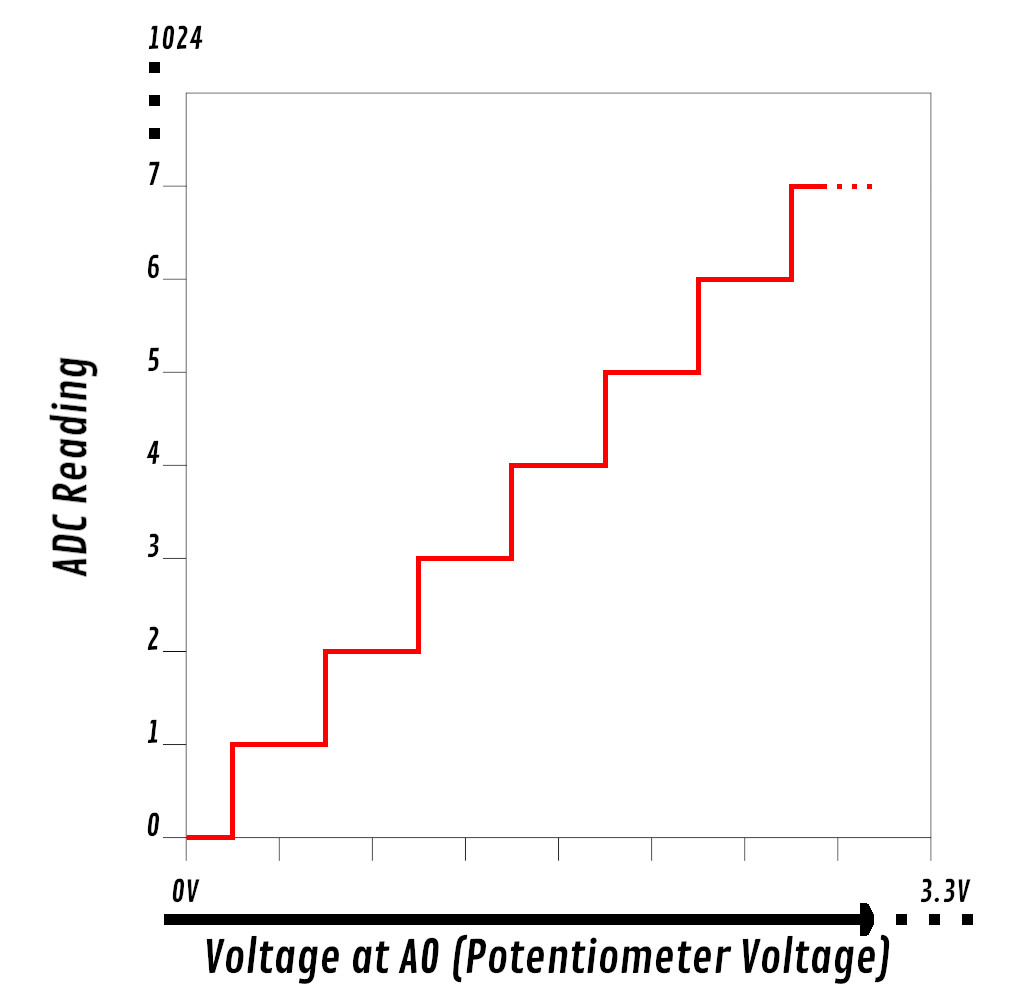
The ADC on the ESP8266 is 10 bit, so there are 1023 possible values that can be read from it. The following image gives a visualization of how the potentiometer’s voltage is converted to a number.
This graph is illustrates how the voltage at A0 is converted to a 10 bit number. Each increment on the horizontal axis is 3.3/1024 volts. It's important to note that the ADC on the ESP8266 only allows a range of 0 to 1V, but a voltage divider built into the NodeMCU changes this range from 0 to 3.3V.
 |
The following code initializes pin ADC0 which allows us to read values from the potentiometer.
Enter the following code into the Thonny editor and save it to your NodeMCU as “main.py”. Then press the restart button on your microcontroller.
from machine import ADC

pot = ADC(0)
To read the value from the ADC we use the read function. Try turning the potentiometer dial to different positions and enter adc.read() into the Thonny repl to get values. Make sure to call read at each of the potentiometers extremes. You will likely notice that you do not get a full 10 bit range of values. I found that my upper extreme reading was 1024 and my lower extreme reading was 18.
Putting it All Together
In this guide we went over the basics of PWM and using the ADC. The goal for this final exercise is for you to create a dimmer using PWM and the ADC. Below is a list of objectives.
- Every 100 milliseconds, set the LED power from GPIO5 to the proportional value of the potentiometer on ADC0.
- When the reading from the potentiometer is at the lowest extreme, the LED should be supplied 0% average power.
- When the reading from the potentiometer is at the highest extreme, the LED should be supplied 100% average power.
- I encourage you to not use a infinite loop, especially if you have already gone through the Timers and Interrupts with a NodeMCU and MicroPython guide. Use a timer instead.
- Initialize LED’s frequency to the maximum allowed, 1000 Hz, and leave it there for the duration of your program.
Hints:
- Below is a helper function that will return a float value between 1.0 and 1.0 when given the current value, the lowest extreme, and the highest extreme.
def pot_percent(val, lower_limit, upper_limit):
  if val > upper_limit:
      val = upper_limit
  elif val < lower_limit:
      val = lower_limit

  total_range = upper_limit - lower_limit

  return (val-lower_limit)/total_range
Below is a demonstration of the program. Good luck!
An LED connected to GPIO5 and a potentiometer connected to ADC0.
 |
Click here to view a solution.
from machine import Pin, PWM, ADC, Timer

POT_LOWER_EXTREME = 18
POT_UPPER_EXTREME = 1024

pwm_led = PWM(Pin(5), freq=1000)
pot = ADC(0)

def pot_percent(val, lower_limit, upper_limit):
    if val > upper_limit:
        val = upper_limit
    elif val < lower_limit:
        val = lower_limit

    total_range = upper_limit - lower_limit

    return (val-lower_limit)/total_range

def set_dimmer(pin):
    pwm_led.duty(int(pot_percent(pot.read(), POT_LOWER_EXTREME, POT_UPPER_EXTREME) * 1023))

timer = Timer(-1)
timer.init(period=100, mode=Timer.PERIODIC, callback=set_dimmer)
Next guide: RTC and Deep Sleep with a NodeMCU and MicroPython
1
Derivative of “Pulse Width Modulation.” Pulse Width Modulation, SparkFun, learn.sparkfun.com/tutorials/pulse-width-modulation/all. Link