Prerequisite Guides
Supplemental Guides
You Will Need
| ESP8266 NodeMCU |
| MicroUSB Cable |
| Computer running Windows, Linux, or MacOSX |
| Breadboard |
| LED |
| 46Ω - 100Ω Resistor |
| 2 Push Buttons |
| Jumper Wires |
Setup
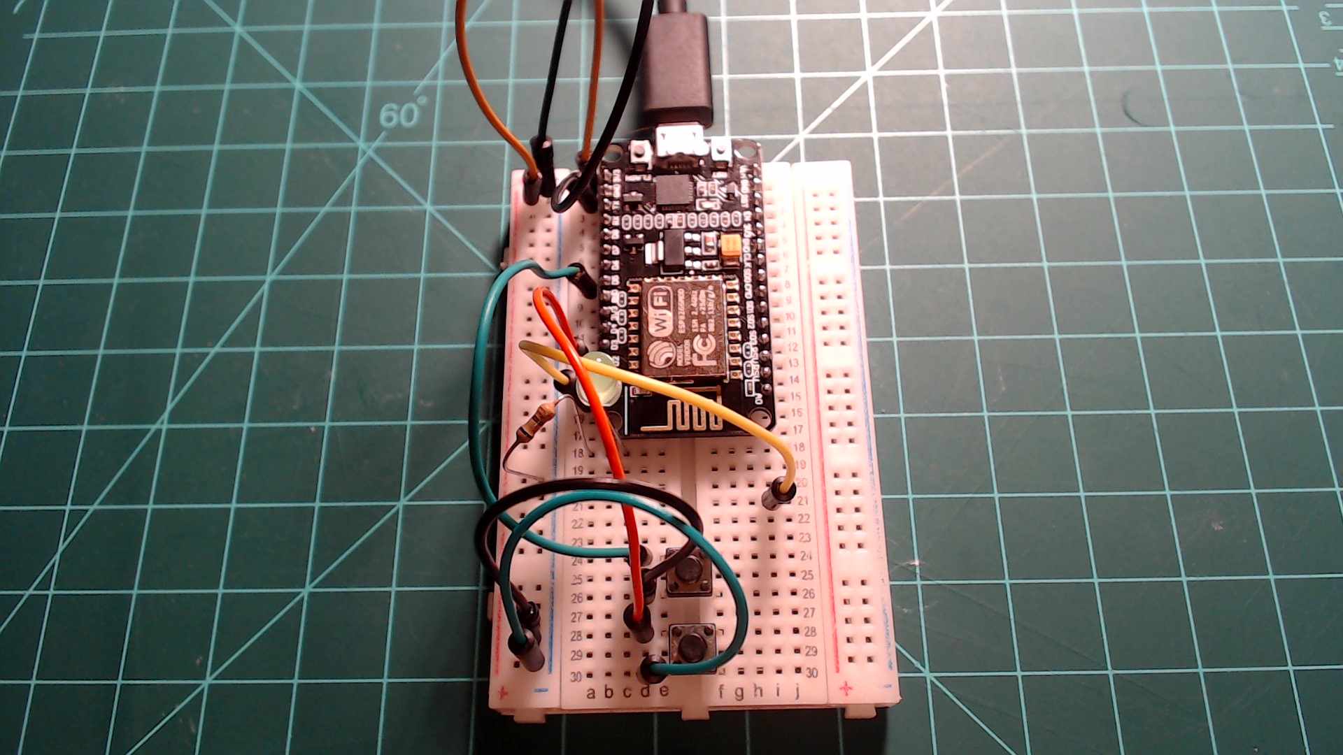
Connect one of the 3V3 pins on the NodeMCU to a breadboard rail and one of the GND pins on the NodeMCU to another rail. Connect an LED to GPIO5 in series with the resistor going to the GND rail. Connect one button to GPIO4 (D2) and the second button to GPIO14 (D5). Connect the other side of both of these buttons to the GND rail. Lastly, connect one end of a jumper wire to GPIO16 (D0) and connect the other end to an empty breadboard row.
Two buttons, an LED, and a jumper wire connected to GPIO16 (D0).
 |
RTC (Real Time Clock)
A RTC, or Real Time Clock, is a circuit that keeps track of real world time (years, months, days, hours, seconds, etc). It achieves this through the use of a crystal oscillator. The ESP8266 has a RTC built-in. In this section we will go over how to set the RTC’s time, check the time, and some of the limitations of using the built-in RTC with MicroPython.
Initializing the RTC
Not including the import, initializing the RTC and setting the time manually takes two lines of MicroPython code, shown below. The first line creates a RTC object and sets it to a variable. The second line sets the time using a tuple containing elements in this order: year, month, day, day of the week, hour, minute, second, millisecond. The following elements for the tuple parameter indicate how to set the time to 2:00:00 PM on the 19th of February, 2020:
- Year: 2020
- Month: 2
- Day: 19
- Day of the week: 0 (Automatically calculated from other data.)
- Hour: 14
- Minute: 0
- Second: 0
- Millisecond: 0
Enter the following code into the Thonny editor and save it to your NodeMCU as “main.py. Press the restart button on the NodeMCU to run this code.
from machine import RTC

rtc = RTC()
rtc.datetime((2020, 2, 19, 0, 14, 0, 0, 0))
Checking the Time
The RTC time can be checked by calling the same datetime command, but with no parameters. You can enter the following line into the REPL to check the current time.
You should see that the time has changed depending on how long you waited before calling the function. If you followed along and set the RTC to 2/19/2020 you should also see that the 4th element, the day of the week, has changed from 0 (Monday) to 2 (Wednesday). You do not need to worry about setting the exact day of the week. It will be automatically found and set.
Limitations
The RTC built-in to the ESP8266 along with the MicroPython implementation is far from a perfect timekeeping method. In my personal use, I have noticed that after running the RTC for a day, it will end up being several minutes off from the actual time. That is not to say it is useless. The RTC can be used in combination with the ntptime module to periodically pull an accurate time from a time server to maintain a more accurate time. We will go over using ntptime in an upcoming guide.
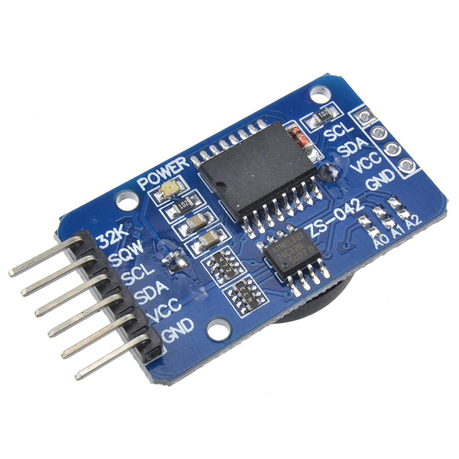
Alternatively an external RTC could be used. A common one, the DS3231, uses and I2C bus to communicate. We will come back to this in a future guide on I2C.
A DS3231 RTC module.[1]
 |
Deep Sleep Mode and the RTC
In the future, you may have an application for your ESP8266 that requires it to be run off of a battery for a long time. The ESP8266 has several power saving modes that could be useful for an application like this. In this section, we will go over the mode that uses the least power, “deep sleep” mode. In deep sleep mode, the only part of the ESP8266 that uses power is the RTC. This results in power consumption being drastically reduced.
Entering Deep Sleep Mode
To prepare your device for deep sleep mode, upload the following code to your device as “main.py” and press the restart button on the NodeMCU to run it. This simply imports the machine module so that deepsleep can be called.
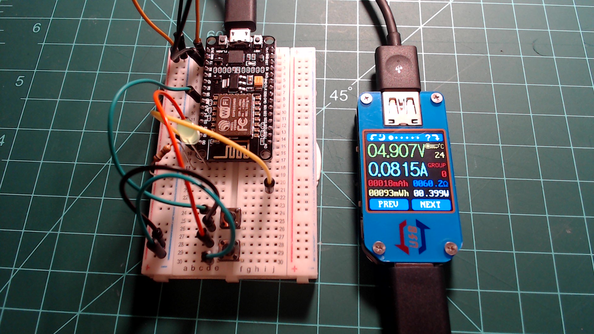
If you have a USB meter feel free to test the values for yourself, otherwise just take my word for it from the following images. Below is an image of usb multimeter in normal mode. You can see that it is drawing 0.399 watts.
The NodeMCU draws 0.399 watts in normal mode.
 |
Now enter “deep sleep” mode by entering the following line in your REPL.
The only change you should notice after entering this command is that the REPL prompt >>> has disappeared. The other change is that the only part of the ESP8266 that is consuming power is the RTC. The image below is the power consumption of the NodeMCU in “deep sleep” mode.
The NodeMCU draws 0.045 watts in deep sleep mode.
 |
Awaking from Deep Sleep Mode
This guide has no final exercise, but this last section on implementing an alarm with the RTC combines everything else taught in this guide together. Like with GPIO pins in the interrupts guide, an IRQ can also be set for the RTC. Just like with the GPIO IRQs, a “trigger” parameter must be set. There is only one available called ALARM0. A “wake” parameter also needs to be set. Since we intend to awaken the device from deep sleep, we set this parameter to machine.DEEPSLEEP. Below is a snippet of code which sets the IRQ with the aforementioned trigger and wake parameters.
rtc.irq(trigger=RTC.ALARM0, wake=machine.DEEPSLEEP)
Unlike the previous triggers for GPIO pins, ALARM0 needs to be configured through code. For this we use the alarm function of the RTC. The first parameter is which alarm to initialize. The second parameter is the amount of time from the current time to set the alarm for in milliseconds. Below is a snippet of code which uses the alarm function of the RTC to initialize ALARM0 for 5000 milliseconds.
rtc.alarm(RTC.ALARM0, 5000)
Waking the ESP8266 in this way is equivalent to pressing the restart button on the NodeMCU. For this reason, the jumper from GPIO16 needs to be connected to the RST pin on the NodeMCU after pressing the restart button an initial time to run the code. A signal from GPIO16 to the RST button is what restarts the ESP8266.
I encourage you to go through the following code line-by-line so that you understand what is happening. This code demonstrates how the RTC continues to run, even in deep sleep mode. After understanding the code, copy it into the Thonny editor, and save it to your device as “main.py”. Press the restart button on the NodeMCU and then immediately plug the wire going from GPIO16 into the pin labeled RST on the breadboard before doing anything else. Below is an itemized list of what the code does:
- Initialize the LED on GPIO5 as an output.
- Initialize two buttons on GPIO4 and GPIO14 as inputs with pull up resistors.
- Initialize the RTC with an IRQ to trigger on
ALARM0 to wake the ESP8266 from deep sleep
- When the button connected to GPIO4 is pressed (the bottom button), the RTC’s datetime is set to 2 PM on 2/19/2020
- When the button connected to GPIO14 is pressed (the top button),
ALARM0 is set 5000 milliseconds and the ESP8266 enters deep sleep mode
- Print the current time from the RTC
- As long as the program is running blink the LED once every second with a timer
import machine
from machine import Pin, RTC, Timer

led = Pin(5, Pin.OUT)
datetime_button = Pin(4, Pin.IN, Pin.PULL_UP)
deepsleep_button = Pin(14, Pin.IN, Pin.PULL_UP)

rtc = RTC()
rtc.irq(trigger=RTC.ALARM0, wake=machine.DEEPSLEEP)

def debounce(pin):
    prev = None
    for _ in range(32):
        current_value = pin.value()
        if prev != None and prev != current_value:
            return None
        prev = current_value
    return prev


def set_time_callback(pin):
    d = debounce(pin)

    if d == None:
        return
    elif not d:
        rtc.datetime((2020, 2, 19, 0, 14, 0, 0, 0))
        print("RTC datetime set: " + str(rtc.datetime()))

def deepsleep_callback(pin):
    d = debounce(pin)

    if d == None:
        return
    elif not d:
        rtc.alarm(RTC.ALARM0, 5000)
        machine.deepsleep()

datetime_button.irq(trigger=Pin.IRQ_FALLING, handler=set_time_callback)
deepsleep_button.irq(trigger=Pin.IRQ_FALLING, handler=deepsleep_callback)

print("\n" + str(rtc.datetime()))

timer = Timer(-1)
timer.init(period=1000, mode=Timer.PERIODIC, callback=lambda t: led.value(not led.value()))
On every reset the current RTC time is printed to the REPL. You should notice that the RTC continues to count time across resets.
Check your REPL to see the continuity of the RTC.
 |
Next guide: Introduction to Networking and ntptime with a NodeMCU and MicroPython
1
DS3231 on Amazon Link