This guide goes over the assembly process of one of our Atlas kits. If you wish to purchase one of these kits or want more information about the Atlas kit click here.
Prerequisite Guides
Supplemental Guides
You Will Need
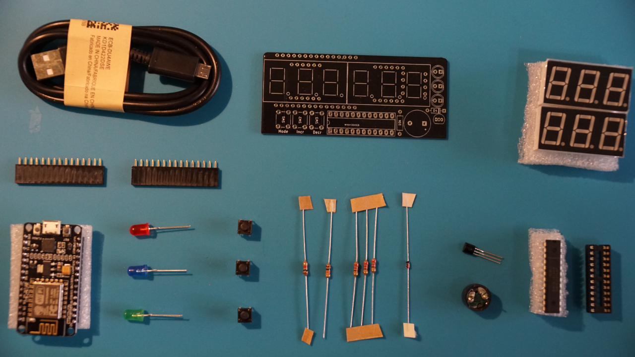
Atlas Kit:
A microUSB cable comes with the Atlas kit, but is not required in the assembly process.
 |
| Micronote Atlas PCB |
1 |
| ESP8266 NodeMCU |
1 |
| 1x15 Female Header |
2 |
| Passive Buzzer |
1 |
| Multicolored LEDs |
3 |
| MAX7219 IC |
1 |
| 24 Pin DIP IC Socket |
1 |
| 6mm Pushbutton |
3 |
| 3 Bit Common Cathode 7-Segment Display |
2 |
| S8550 PNP Transistor |
1 |
| 1N4148 Diode |
1 |
| 10k Resistor |
1 |
| 1k Resistor |
1 |
| 220Ω Resistor |
3 |
Recommended tools for assembling your kit.
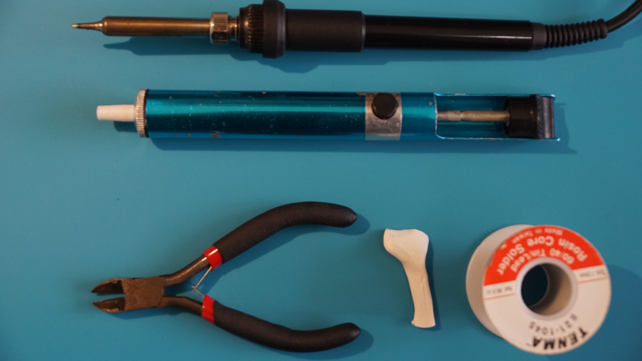 |
| Soldering Iron |
| Solder |
| Solder Sucker |
| Wire Cutters |
| Mounting Putty |
Assembling Your Kit
In this section we will go over the process of soldering the various components onto the Atlas PCB. To aid this process I use mounting putty to hold the components in place while I’m soldering. This is a personal preference of mine that works well for me. If you have found better way of doing it, then you should use your way. After holding a component in place with mounting putty, I then solder each component onto the PCB with my soldering iron and solder. Then I snip off the leads with the wire cutters and remove the putty.
It is very important that you solder the parts in the order that this guide indicates. Failure to do so will make assembly much more difficult or nearly impossible to complete without restarting.
1. Resistors
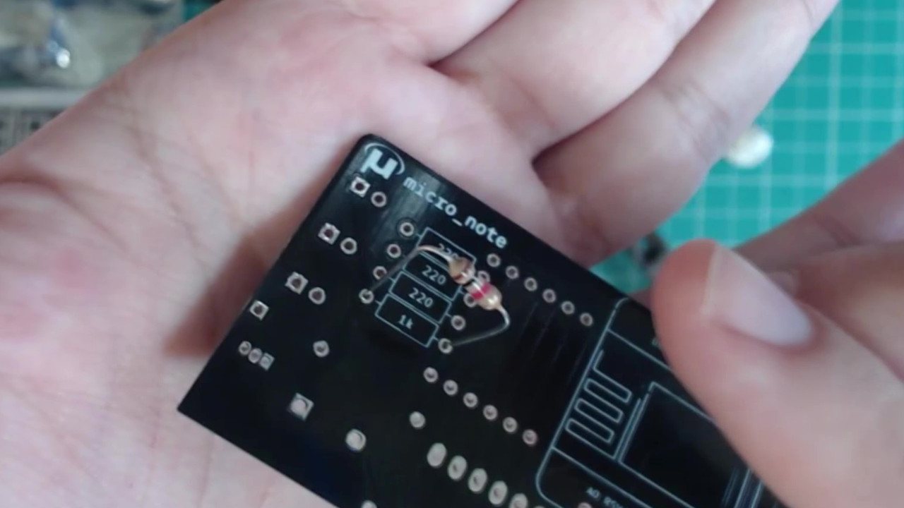
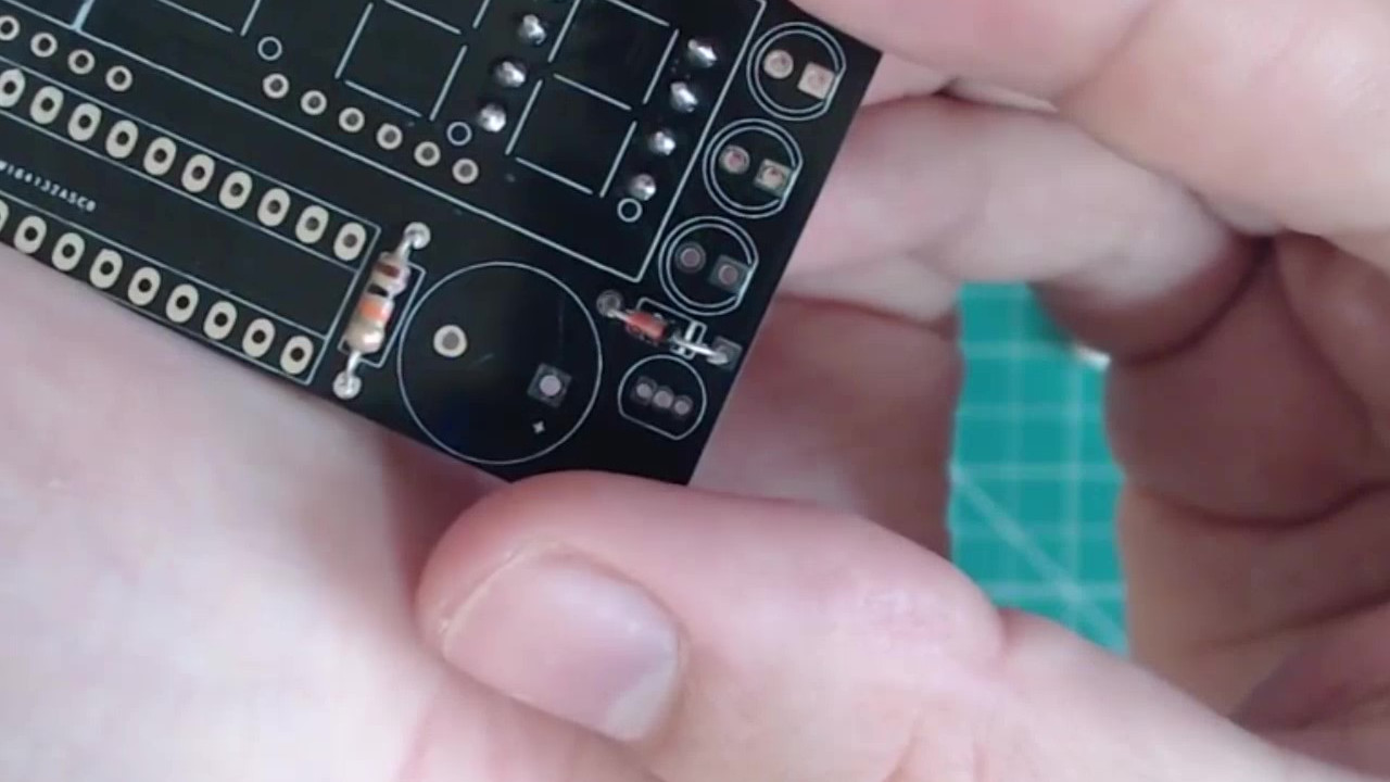
Insert the 1k resistor into the the designated holes on the back of the PCB. For resistors the orientation in which you place the resistor does not matter.
The 1k resistor loosely in place on the PCB.
 |
Hold the resistor in place with the mounting putty. Then, flip the PCB over and solder the leads of the resistor in place from the other side.
Putty placed on top of the resistor to hold it in place.
 |
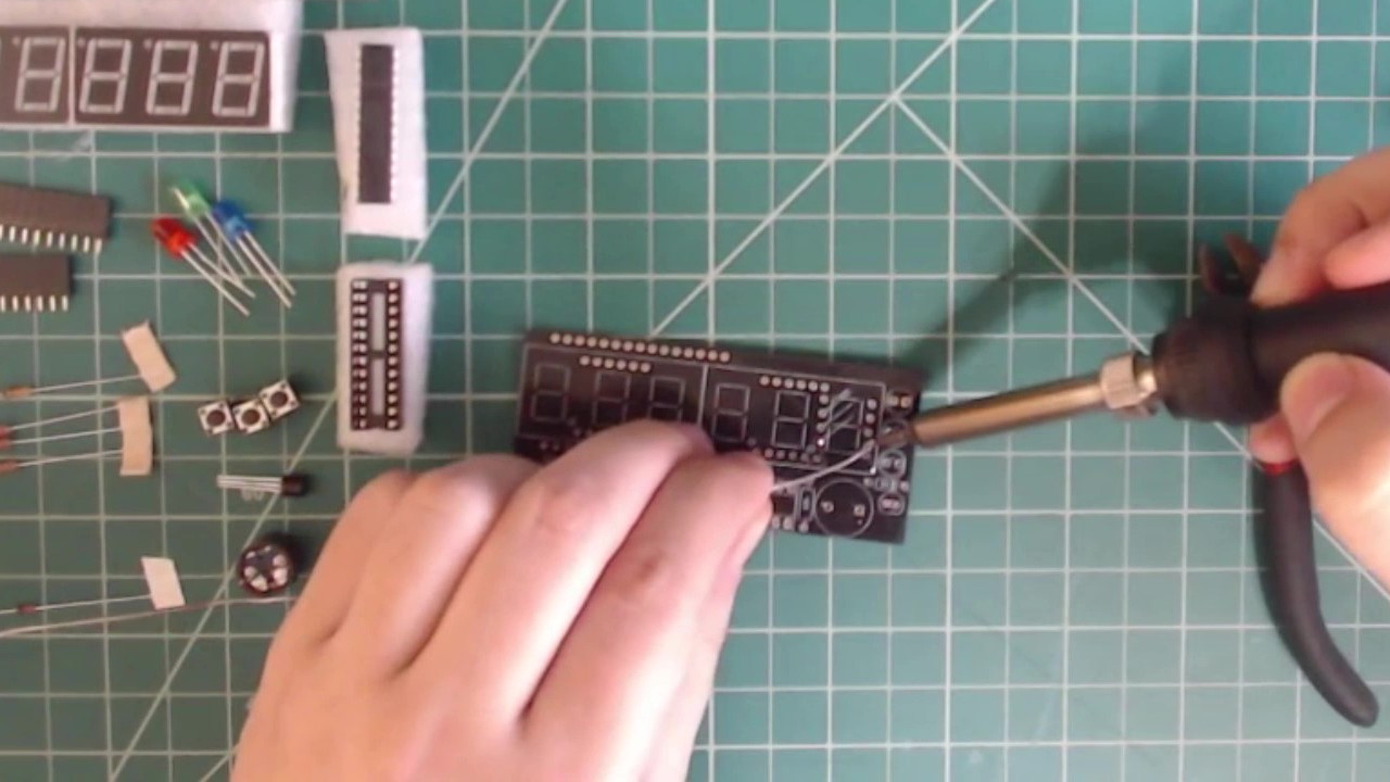
Now, solder the resistor in place.
Solder the resistor in place.
 |
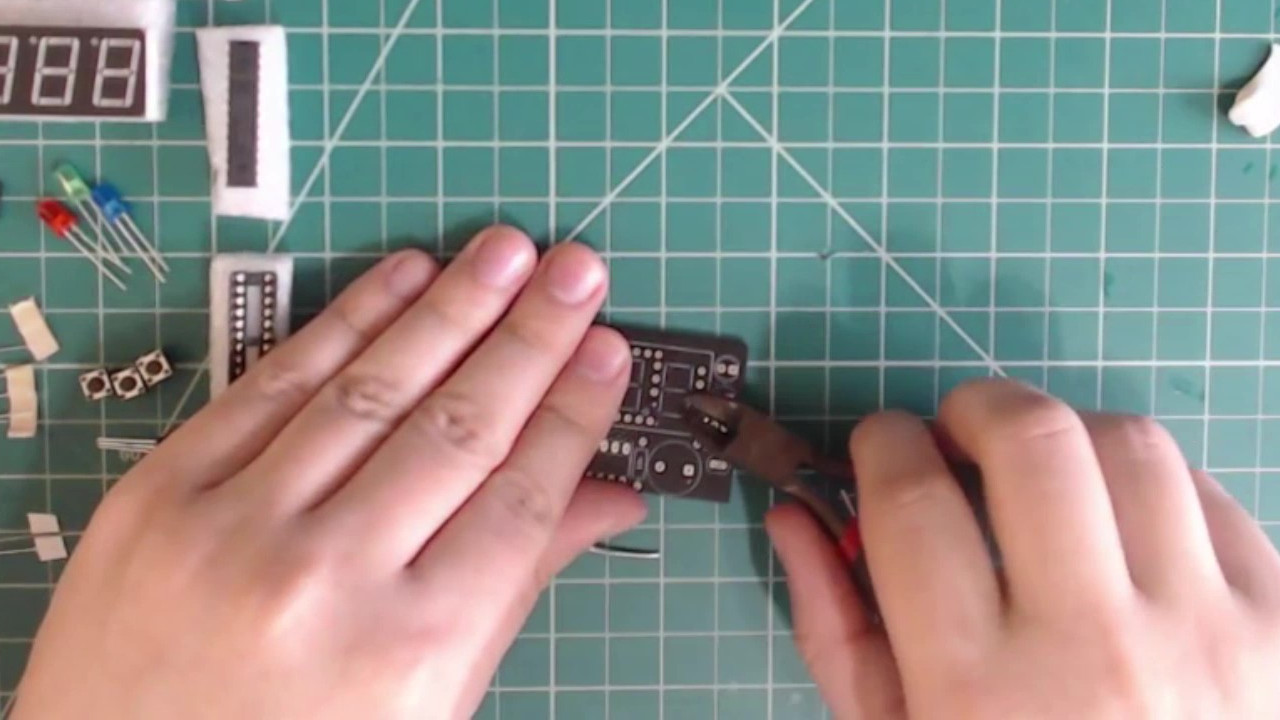
After it is cleanly and securely in place snip the leads with your wire cutters.
Snip the excess leads.
 |
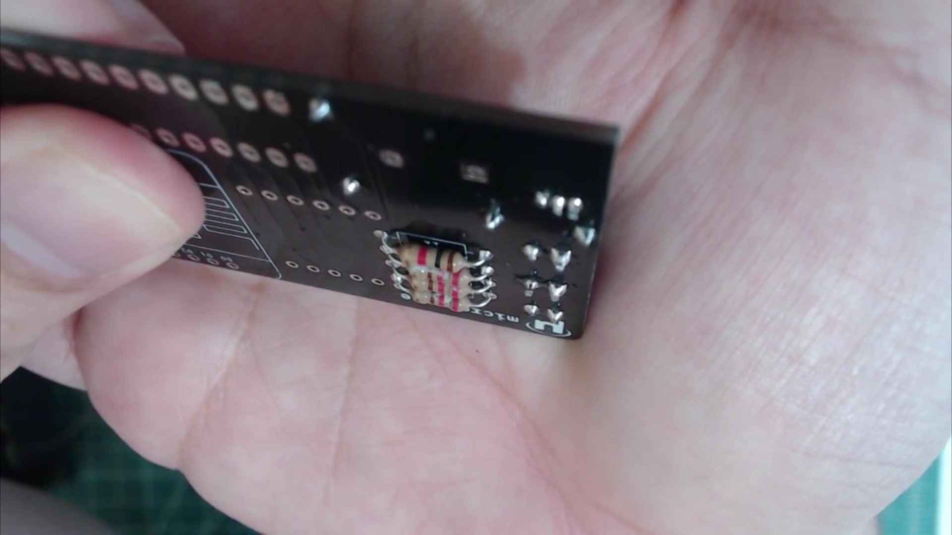
Repeat this process with the three 220Ω resistors above the 1k resistor.
The 1k resistor and three 220Ω resistors soldered in place.
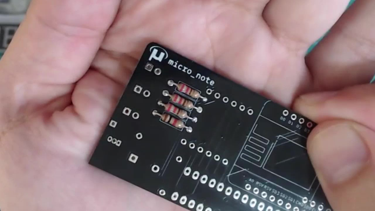 |
Flip the PCB over and solder the last resistor, which has a value of 10k, to the designated location on the front.
Solder the 10k resistor in the indicated location on the PCB.
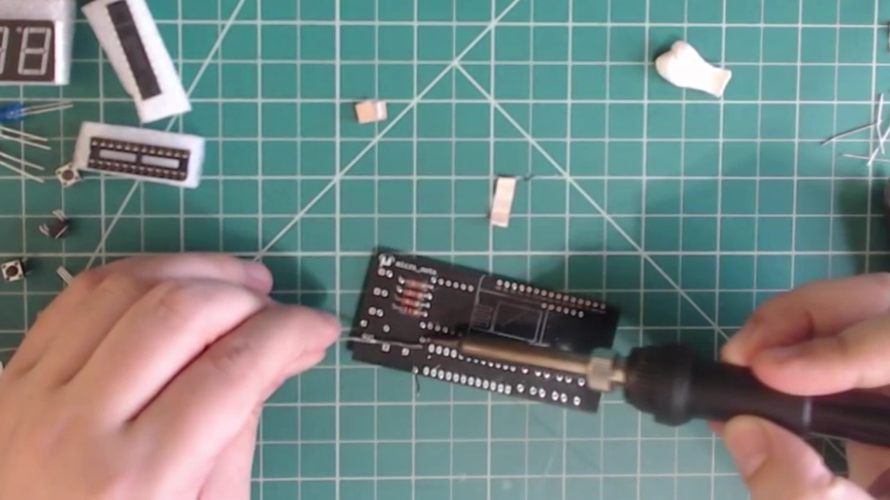 |
2. Diode
Unlike with the resistor, the orientation of the diode matters. Make sure that the black end of the diode is on the right side (over the white bar) before soldering it in place.
Take the diode and place it in the designated holes on the front of the PCB in the correct orientation. Hold the diode in place and solder it to the PCB.
The diode must be soldered in the orientation shown here.
 |
3. LEDs
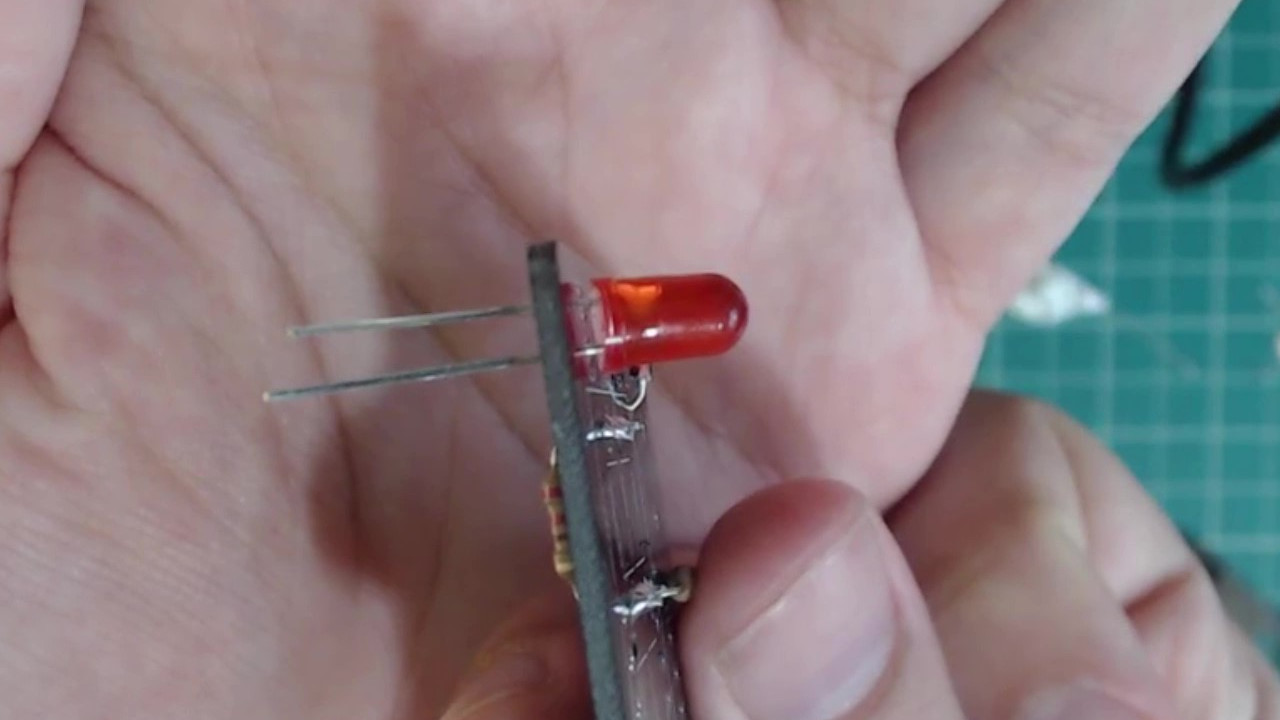
The LEDs also need to be soldered onto the PCB with the correct orientation. The LED has two leads of different length. Make sure that the short lead is closer to the edge of the PCB for each LED.
The correct orientation for an LED.
 |
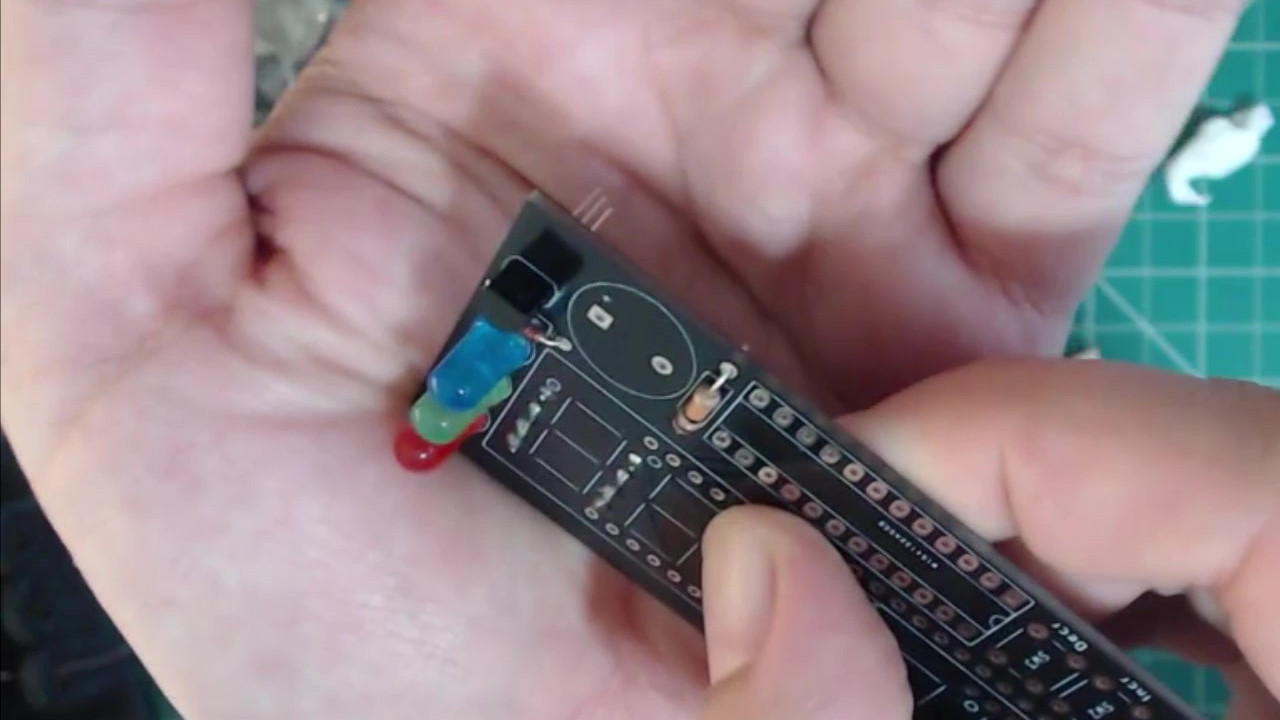
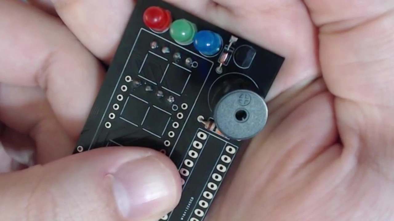
From top to bottom, solder in place the red, green, and blue LEDs in the correct orientation.
The LEDs soldered onto the PCB in the correct order.
 |
4. Transistor
Make sure to line up the transistor so that the flat side is facing the bottom of the PCB as indicated.
The transistor inserted into the PCB correctly.
 |
Hold the transistor in place and then solder the transistor to the PCB. The leads of the transistor are closer together, so if you accidentally bridge two of the leads when soldering make sure to clean it up and use the solder sucker if you need to.
Make sure that none of the transistor's leads are connected before continuing.
 |
5. Buzzer
Place the buzzer into the PCB with the plus sign on the side indicated by the PCB (towards the edge). Then secure it place and solder it on.
Buzzer placed into the PCB correctly.
 |
6. IC Socket
Next, place the IC socket into the indicated spot.
The IC socket on the PCB.
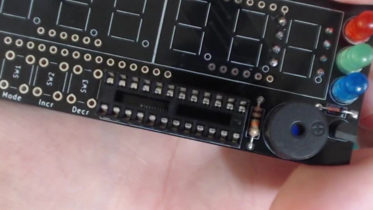 |
Secure it in place and then solder it on.
The IC socket soldered in place.
 |
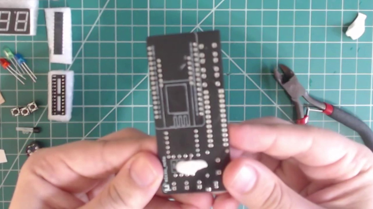
In this step we will only be soldering the bottom 1x15 header into place. The easiest way to do this is to take your NodeMCU and put both headers onto the two rows of leads.
A header placed onto each of the NodeMCU's pin rows.
 |
Place the NodeMCU with the headers attached onto the PCB in the indicated location. This is the best way to ensure that the headers are aligned straight.
NodeMCU with the headers attached placed onto the PCB.
 |
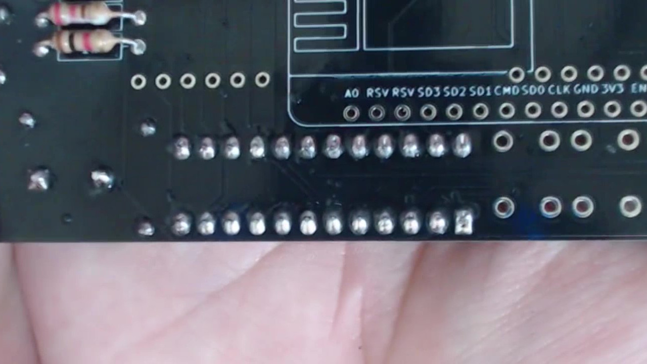
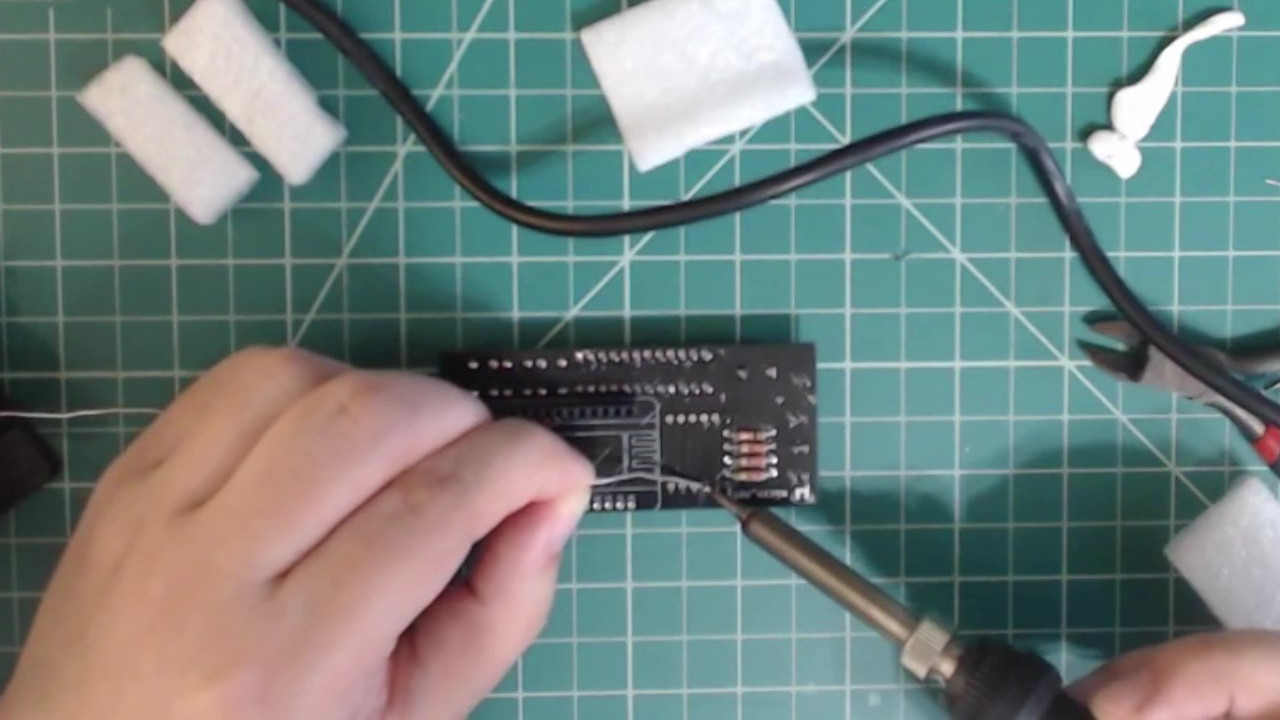
Solder only the pins from the bottom header onto the PCB. Then gently remove the NodeMCU with the top header still attached from the PCB.
Solder only the bottom header pins.
 |
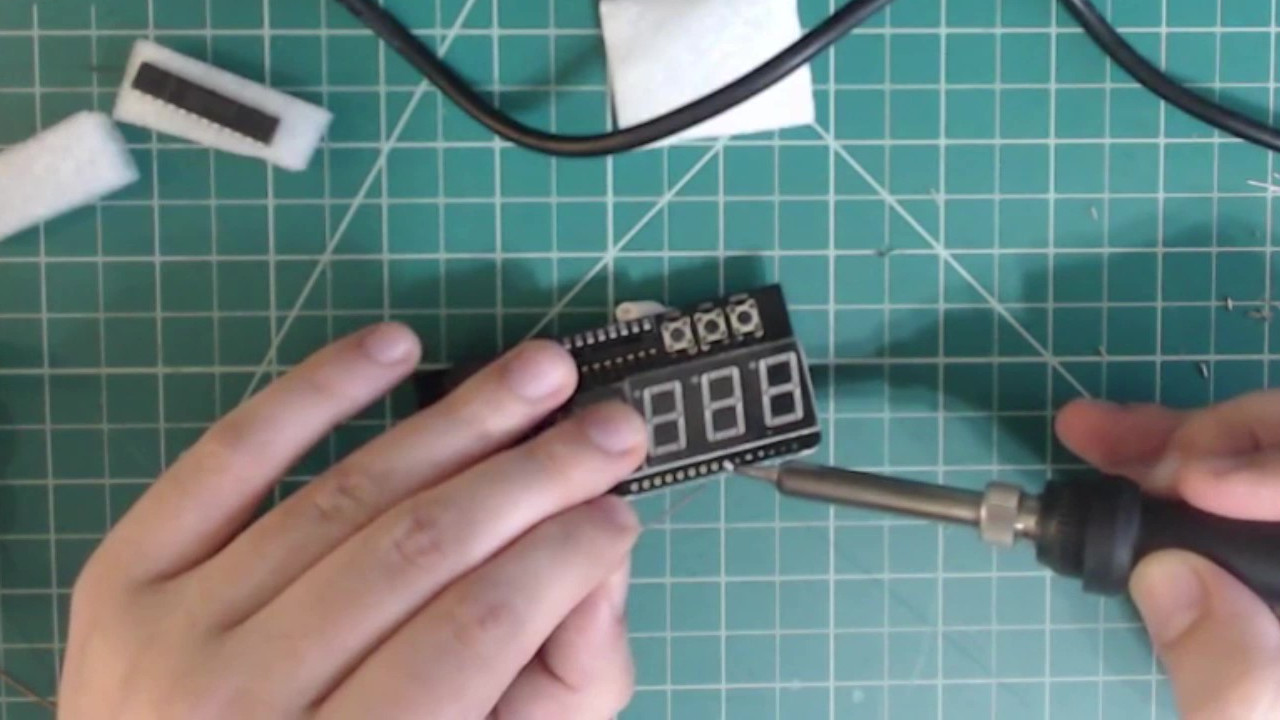
Place all of the buttons onto the PCB. Due to the shape of the buttons’ leads, if you firmly press them into the their designated holes, they will stay in place.
Buttons placed onto the PCB.
 |
Solder all of the buttons in place.
Solder the buttons onto the PCB.
 |
9. 7-Segment Displays
Insert the 7-segment displays into the designated spot. Make sure that the decimal points are towards the bottom of the PCB.
7-segment displays inserted into the PCB.
 |
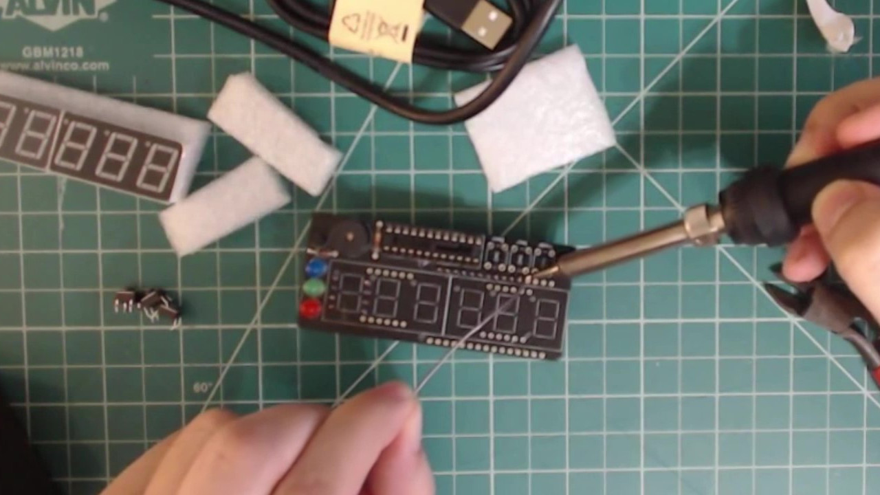
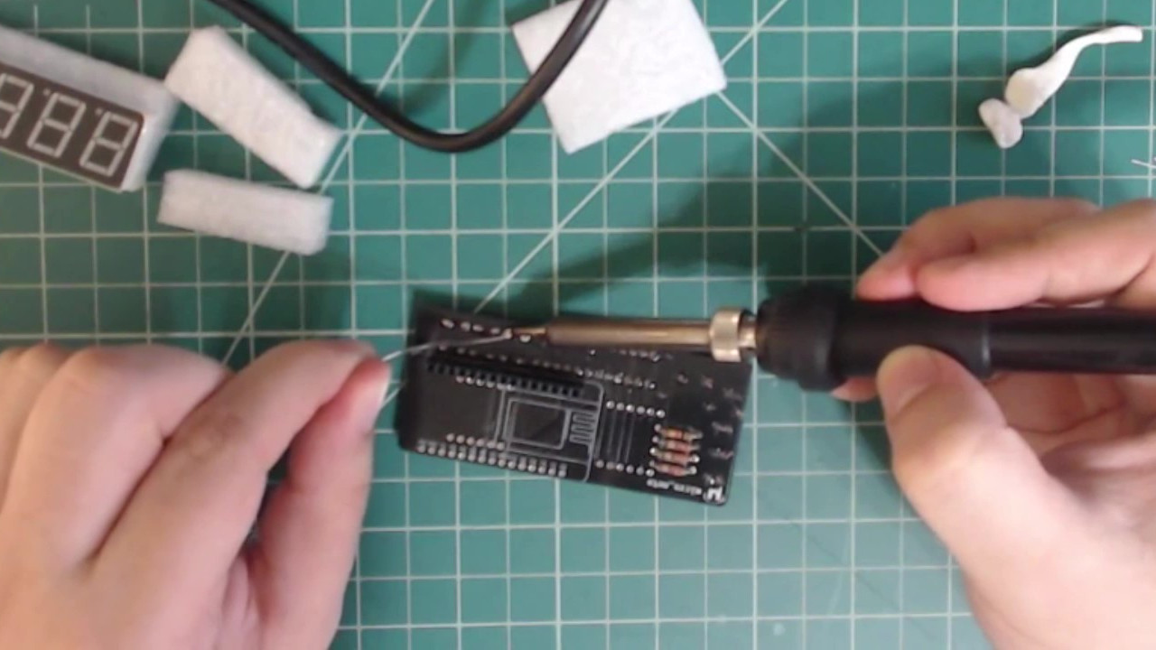
Flip the PCB over and solder all of the pins in place.
Solder the 7-segment displays onto the PCB.
 |
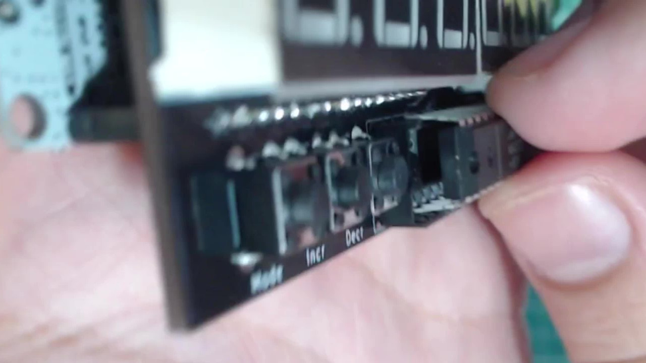
Place the NodeMCU with the top header still attached onto the PCB, placing the bare row of pins into the already attached bottom header.
NodeMCU placed back onto the PCB with the headers.
 |
Solder the pins from the top header into place.
Solder the top header pins.
 |
11. MAX7219 IC
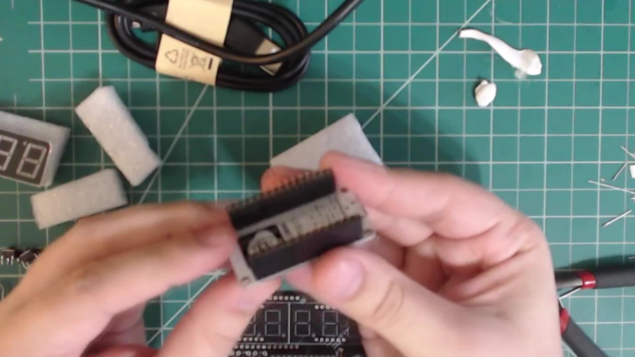
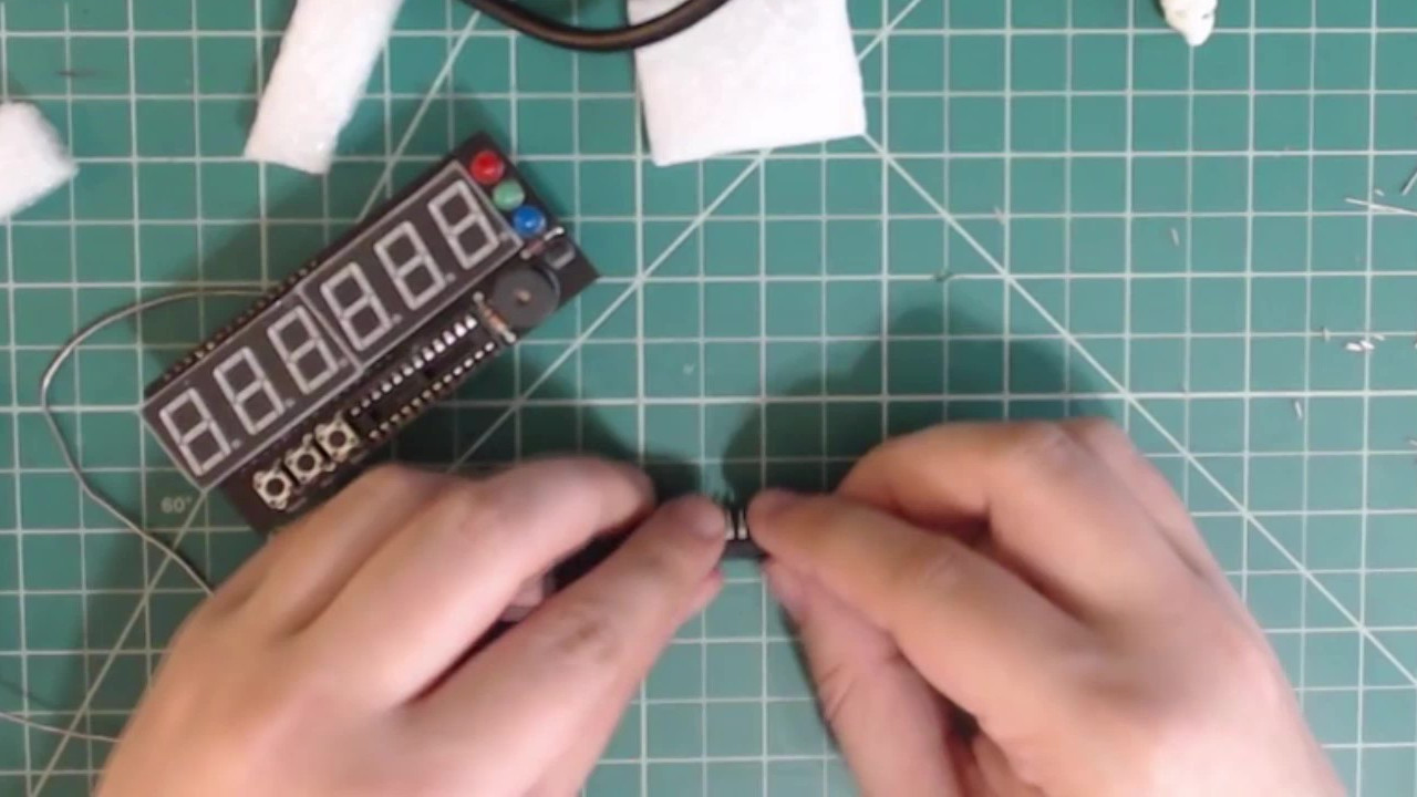
The MAX7219 IC does not need to be soldered. Instead it is inserted into the IC socket that was soldered previously. The pins on the MAX7219 chip are bent slightly outward so we will need to bend them back so they are straighter.
Pins on the MAX7219 IC are bent slightly outwards.
 |
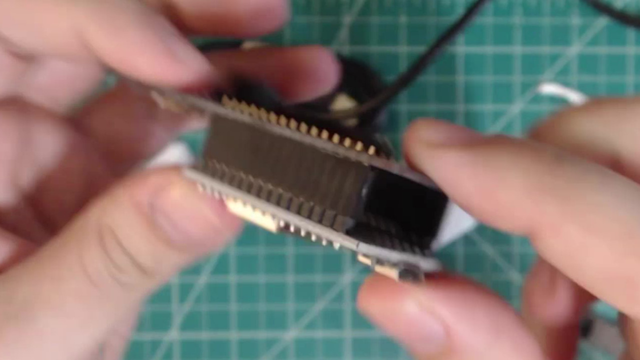
Using a level surface (or any other method you find works), gently bend the pins little by little until they are straight. Do this for both sides of the IC.
Gently bend the pins back to being straight. I do this by pressing the IC against my table.
 |
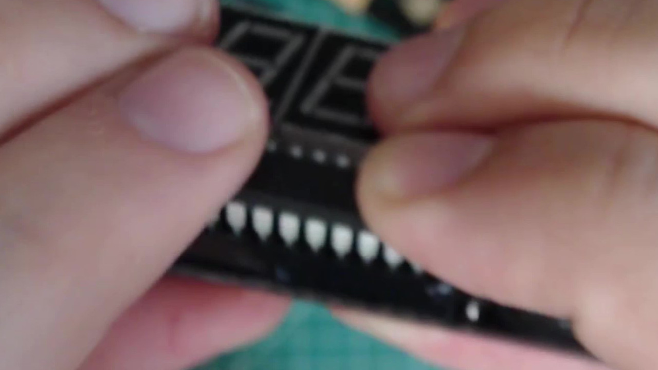
Line the IC up with the socket. Make sure that each pin lines up with a hole before continuing!
Line the up the straightened IC pins with the socket.
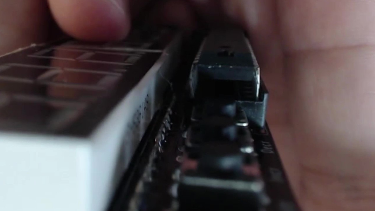 |
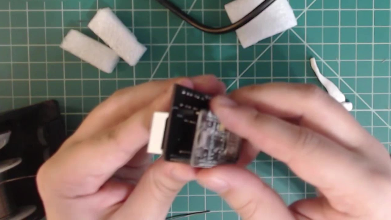
Once you are sure that the IC’s pins are lined up with the socket. Firmly press it inwards.
Press the IC into the socket.
 |
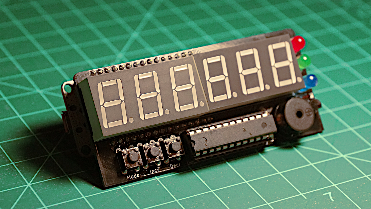
Conclusion
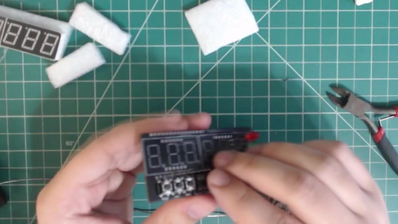
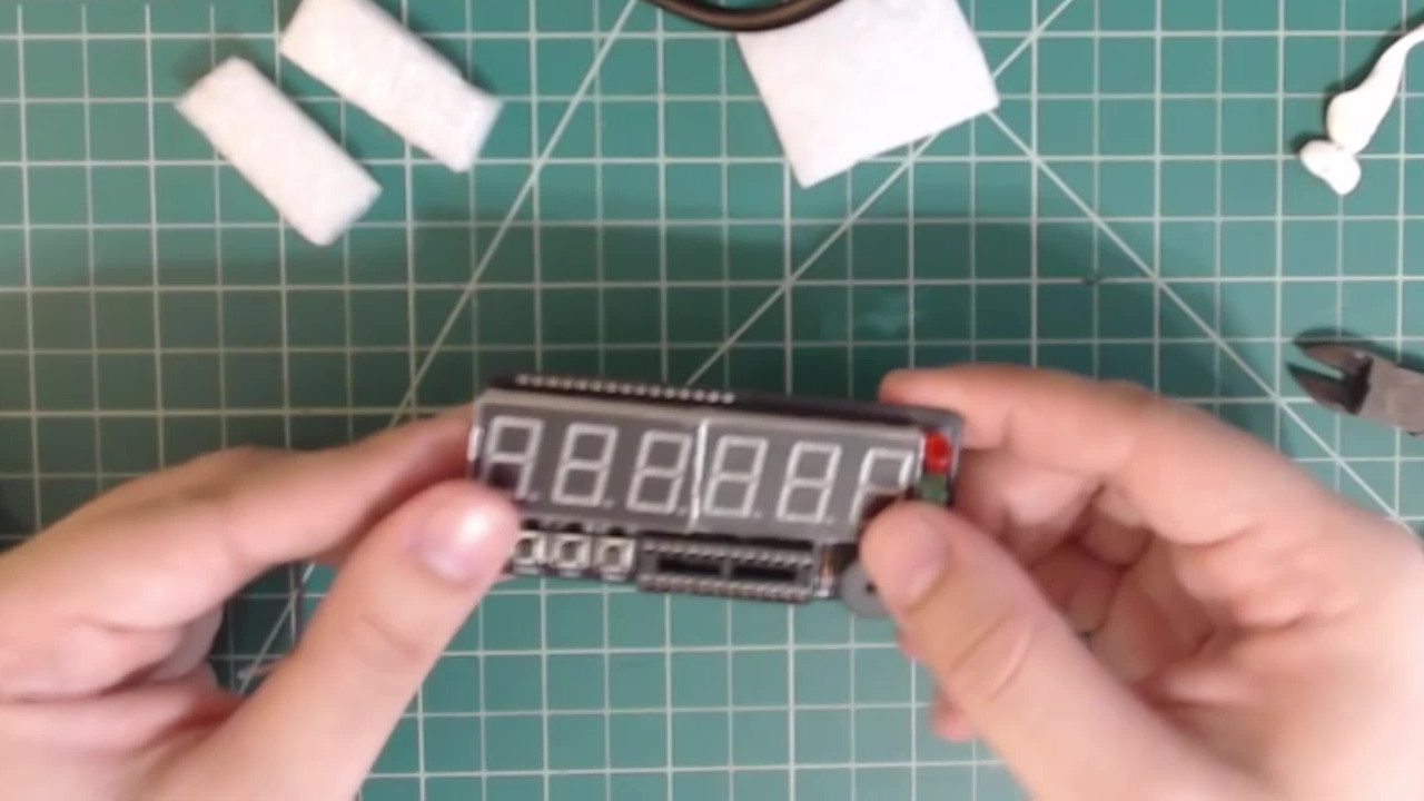
Congratulations! You have assembled your Atlas kit! You are now ready to start programming it.
A completed Atlas kit.
 |
Next guide: Setting Up your Atlas Device