Prerequisite Guides
Supplemental Guides
You Will Need
| ESP8266 NodeMCU |
| MicroUSB Cable |
| MPU6050 IMU Module |
| 128x64 SSD1306 OLED Display Module |
| Jumper Wires |
| Computer running Windows, Linux, or MacOSX |
Setup
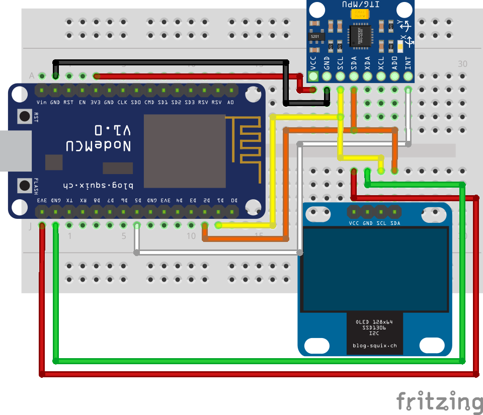
If you do not have a NodeMCU flashed with MicroPython, or you do not know how to upload programs to a NodeMCU in Thonny, then I recommend reading the Hello MicroPython guide before continuing further with this guide. Below is a diagram of the entire setup needed to complete this guide.
Setup with the NodeMCU connected to the MPU6050 IMU and the SSD1306 display.
 |
NodeMCU
Start by plugging your ESP8266 NodeMCU into one end of the breadboard so that its microusb port is on the edge of the breadboard. Make sure that there is one row of open breadboard pins on both long sides of the NodeMCU.
MPU6050 IMU
On one of the long sides of the breadboard, plug in the MPU6050 IMU. Make the following connections using jumper wires:
| NodeMCU |
MPU6050 |
| 3V3 |
VCC |
| GND |
GND |
| D1 |
SCL |
| D2 |
SDA |
| D5 |
INT |
SSD1306 Display
On the other long side of the breadboard plug in the SSD1306 display. Make the following connections using jumper wires:
| NodeMCU |
SSD1306 |
| 3V3 |
VCC |
| GND |
GND |
| D1 (or SCL on the MPU6050) |
SCL |
| D2 (or SDA on the MPU6050) |
SDA |
Completed Setup
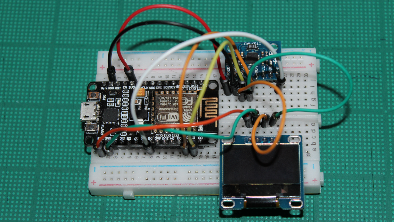
You are ready to continue into the guide if your setup resembles the image below.
Completed breadboard setup.
 |
What is I2C?
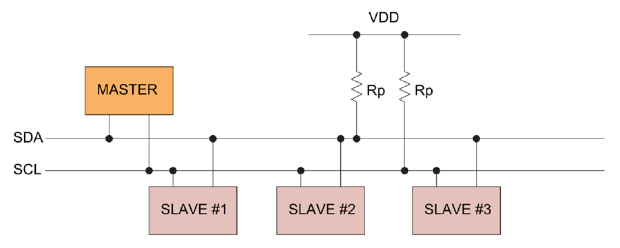
I2C, pronounced (I-squared-C), stands for “Inter-Integrated Circuit” and is a type of communications bus. “Communications bus” in electronics refers to a system that allows different electronics components to transfer data. The I2C bus transfers data through the use of two bidirectional lines called SDA and SCL. SDA stands for “serial data” and SCL stands for “serial clock”. Both of these lines require pull-up resistors.
Schematic of an I2C bus.[1]
 |
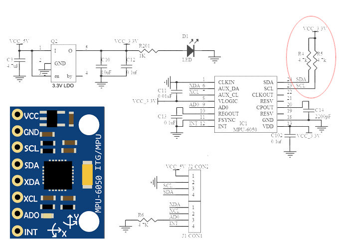
The MPU6050 and SSD1306 modules have these pullup resistors included. Below is a schematic of the MPU6050 IMU module.
Pullup resistors in the schematic for the MPU6050 IMU.[2]
 |
There are two types of devices that can use an I2C bus. “Master” devices always control the SCL line and inititiate data transfers on the SDA line. “Slave” devices can only respond to a master device. Most commonly there are many slaves and a single master on a given I2C bus, however, multiple masters on a single I2C bus is possible, but this is outside the scope of this guide.
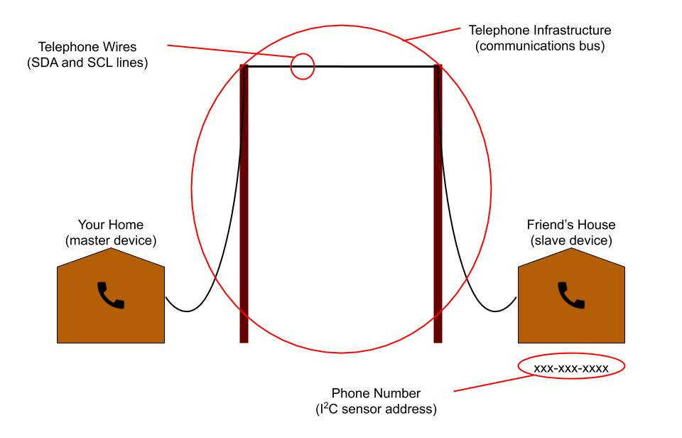
A single I2C bus using 7 bit addressing can support 128 devices with one master device and 127 slave devices. Each slave device has a unique 7 bit address which is used by a master device to specify to which slave it wants to read from or write to. An analogy for an I2C bus is a telephone line. Many houses can be connected to the telephone network, but dialing a number specifies for which house a message is for, just like an I2C address specifies to which slave device a message is for.
Telephone line analogy for I2C devices.
 |
Datasheets!
In the previous guides, components were used that were simple enough to not require use of their respective datasheets. However, the components used in this guide (the MPU6050 IMU and SSD1306 display) are too complex to use without use of their datasheets. You can find links to the datasheets used in this guide below.
The next section of this guide will frequently reference these datasheets.
Communicating with the MPU6050 IMU
This section will go over use of the MPU6050 IMU. IMU stands for “inertial measurement unit”. The MPU6050 IMU provides accelration, gyroscope, and temperature data. A typical application for an IMU is something like a multirotor UAV where it is very important to have a constant stream of inertial data.
Read the Temperature
Let’s start by communicating with the MPU6050 IMU to get the ambient temperature of the room you are in. Plug the ESP8266 NodeMCU into your computer and open Thonny. Then, navigate to “Run > Select Interpreter” to make sure your interpreter is setup for MicroPython on an ESP8266 with the correct port. Press the stop button at the top of Thonny to get an open REPL.
Define the I2C Bus
Let’s start by defining an I2C bus in MicroPython. Enter the following two lines of code into the Thonny REPL to first import Pin and I2C, and then declare a variable called i2c to be an I2C bus using GPIO5 (D1) as SCL and GPIO4 (D2) as SDA.
>>> from machine import Pin, I2C
>>> i2c = I2C(scl=Pin(5), sda=Pin(4))
Determine the Address
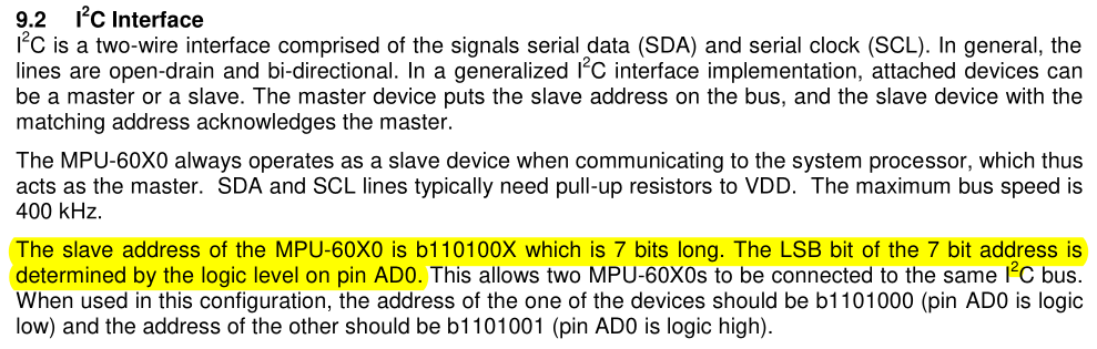
Before the MPU6050 IMU can be communicated with, its device address on the I2C bus must be known. The product specification datasheet indicates that the address is set to either 0b1101000 or 0b1101001 (like in Python, Micronote guides use an “0b” prefix to indicate a binary number) depending on the state of the AD0 pin on the MPU6050. There is no reason to worry about conflicting addresses within the scope of this guide, so the AD0 pin can be left as is to use the address of 0b1101000. 0b1101000 translates to 0x68 in hexadecimal and 104 in decimal.
Section 9.2 of the product specification datasheet is about the I2C interface.
 |
The addresses of devices on the I2C bus can also be checked by using the I2C.scan function. Enter the following code into the Thonny REPL to scan the I2C bus for device addresses.
The function should return a list containing two decimal numbers. These numbers are addresses of the I2C devices on the bus. You should see that one of the addresses is 104 (decimal) which is the address of the MPU6050 IMU. The other address should be 60 and is the address of the SSD1306 display.
Activate the Device
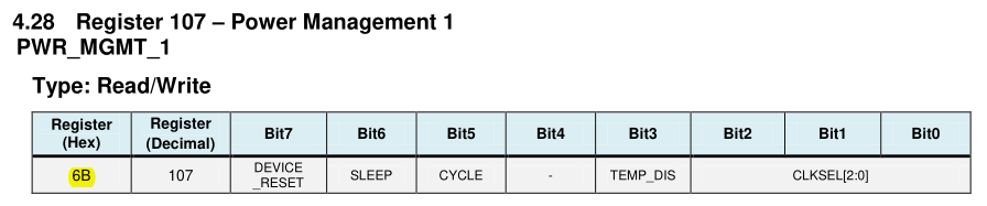
The first thing that needs to be done before getting data from the MPU6050 IMU is to make sure that the device is not in sleep mode. The device can be told to exit sleep mode by setting all of the bits in the PWR_MGMT_1 register to 0. A register is a location in memory that has bits that can be set, cleared, and read. These memory locations can be accessed by using their memory addresses. For the MPU6050, this information can be found on the register map and descriptions datasheet. This datasheet shows that the PWR_MGMT_1 memory address is 0x6B. To the right of the memory address of the register are the functions for each of the bits in the register. Not shown, below this table, there are more details as to what each of these bits do when set or cleared.
Bits in the PWR_MGMT_1 register of the MPU6050 IMU.
 |
To set bits at a particular address in memory, the I2C.writeto_mem function can be used. Enter the following code into the Thonny REPL to set all of the bits in the PWR_MGMT_1 register to 0.
>>> i2c.writeto_mem(0x68, 0x6B, bytes([0]))
Each of the parameters in the I2C.writeto_mem function is itemized below for clarity:
- The first parameter is the address of the slave device on the I2C bus.
- The second parameter is the memory address of the register on the slave device to start writing to.
- The third parameter is the data to write as a
bytes type. A byte is equal to 8 bits and can represented as a two digit hexadecimal number.
Read Temperature Data
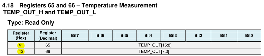
The most recent temperature data is stored in two MPU6050 registers called TEMP_OUT_H and TEMP_OUT_L. TEMP_OUT_H stores the higher part of the temperature data and TEMP_OUT_L stores the lower part of the temperature data. When the values in these two registers are combined correctly they will provide a temperature in degrees celsius.
Bits in the TEMP_OUT_H and TEMP_OUT_L registers of the MPU6050 IMU.
 |
Let’s get the temperature data from the registers. To read data from the an I2C slave device at a particular address in memory, the I2C.readfrom_mem function can be used. Enter the following code into the Thonny REPL to define two variables, temp_h and temp_l, as the values read from the TEMP_OUT_H and TEMP_OUT_L registers respectively.
>>> temp_h = i2c.readfrom_mem(0x68, 0x41, 1)
>>> temp_l = i2c.readfrom_mem(0x68, 0x42, 1)
Each of the parameters in the I2C.readfrom_mem function are itemized below for clarity:
- The first parameter is the address of the slave device on the I2C bus.
- The second parameter is the memory address of the register on the slave device to start reading from.
- The third parameter is the number of bytes to read starting at the given memory address.
Process Temperature Data
Now that the high and low temperature values are stored, they can be combined into a single value.
1. Access Element at Index 0
temp_h and temp_l are each equal to an array of bytes containing one element. To get the integer value out of this array, the element at index 0 needs to be accessed. Below, the temp_h and temp_l values are reset to be equal to their element at index 0.
>>> temp_h = temp_h[0]
>>> temp_l = temp_l[0]
2. Bit Shift Upper Value 8 to the Left
Now, temp_h and temp_l need to be combined into a single number. To do this, temp_h needs to be shifted eight places to the left using the left bitshift operator <<.
3. Combine High and Low Values
Then, the now bit-shifted temp_h can be combined with temp_l using a bitwise OR operator | into a variable called temp_data.
>>> temp_data = temp_h | temp_l
The values read from the TEMP_OUT_H and TEMP_OUT_L registers have now been combined into a single value. Now this number needs to be checked to see if it is negative. The MPU6050 IMU and many binary systems represent negative numbers through the use of a sign bit, which in the case of the MPU6050 IMU, is the left most bit of the binary value in the TEMP_OUT_H register. If the number is negative, a two’s complement needs to be performed on temp_data in order to get the right temperature value. A two’s complement operation consists of flipping every bit in a binary number and then adding 1. Below we have an if statement checking to see if the left most bit is a 1 through the use of a bitwise AND operator &. If the leftmost bit is a 1, then a two’s complement operation is performed on temp_data using the bitwise XOR operator ^.
>>> if temp_data & 0b1000000000000000:
>>>     temp_data = -((temp_data ^ 0b1111111111111111) + 1)
There is one last step to converting this value to a temperature in Celsius and it can be found stated clearly on the datasheet.
Located in section 4.18 of the register map and descriptions datasheet.
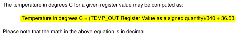 |
The datasheet clearly states that a temperature value in degrees Celsius can be found by dividing the value by 340 and adding 36.53:
>>> temp_c = (temp_data / 340.0) + 36.53
All Steps Summarized in a Function
Below are all of these steps in a single Python function.
def temp_data_to_celsius(temp_h, temp_l):
    temp_h = temp_h[0]
    temp_l = temp_l[0]

    temp_h = temp_h << 8

    temp_data = temp_h | temp_l

    if temp_data & 0b1000000000000000:
        temp_data = -((temp_data ^ 0b1111111111111111) + 1)

    temp_c = (temp_data / 340.0) + 36.53
    return temp_c
This function can be reduced to the code below.
def temp_data_to_celsius(temp_h, temp_l):
    if not temp_h[0] & 0x80:
         return ((temp_h[0] << 8 | temp_l[0]) / 340.0) + 36.53
    return -((((temp_h[0] ^ 255) << 8) | (temp_l[0] ^ 255) + 1) / 340.0) + 36.53
Read Temperature Script
The script below puts all of the steps used above to get and process the temperature data into a single script. Notice that a more generalized function was created to combine the high and low registers by moving the temperature specific constants outside of the combine_register values function. This will reduce the amount of code needed when support for the accelerometer and gyroscope is added. Save this code as “main.py” on your ESP8266 NodeMCU, then press the restart button to run it.
from machine import I2C, Pin
from time import sleep_ms

MPU6050_ADDR = 0x68
MPU6050_TEMP_OUT_H = 0x41
MPU6050_TEMP_OUT_L = 0x42
MPU6050_PWR_MGMT_1 = 0x6B

MPU6050_LSBC = 340.0
MPU6050_TEMP_OFFSET = 36.53


def mpu6050_init(i2c):
    i2c.writeto_mem(MPU6050_ADDR, MPU6050_PWR_MGMT_1, bytes([0]))


def combine_register_values(h, l):
    if not h[0] & 0x80:
        return h[0] << 8 | l[0]
    return -((h[0] ^ 255) << 8) |  (l[0] ^ 255) + 1


def mpu6050_get_temp(i2c):
    temp_h = i2c.readfrom_mem(MPU6050_ADDR, MPU6050_TEMP_OUT_H, 1)
    temp_l = i2c.readfrom_mem(MPU6050_ADDR, MPU6050_TEMP_OUT_L, 1)

    return (combine_register_values(temp_h, temp_l) / MPU6050_LSBC) + MPU6050_TEMP_OFFSET


if __name__ == "__main__":
    i2c = I2C(scl=Pin(5), sda=Pin(4))
    mpu6050_init(i2c)

    while True:
        print(mpu6050_get_temp(i2c))
        sleep_ms(500)
I2C Bus Protocol
This section will explain how the I2C reads and writes we have been making to get the temperature data, are physically sent on the SDA and SCL lines of the I2C bus. A I2C message is composed of “frames” which are inbetween a start condition and a stop condition. The image below is a generic diagram of an I2C message.
Generic diagram of an I2C signal.[3]
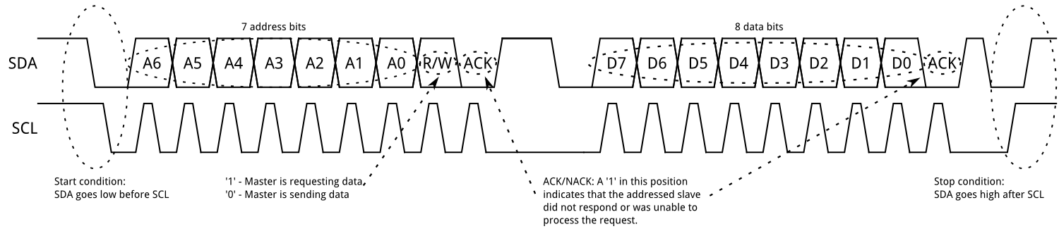 |
Address Frame
All the way on the left there is a start condition indicating that an I2C message is beginning. The start condition is initiated by an I2C “master” by pulling the SDA line low and leaving the SCL line high. Following the start condition the master will begin sending data in an “address frame”. Address frames indicate to which slave the master intends on communicating with. After the 7 bit address, the master will send another bit indicating weather the master wants to read from or write to the slave device. After these 8 bits are sent, the slave device will gain control of the SDA line and will be able to send a final bit either acknowledging what was sent by pulling the SDA line low or not acknowledging what was sent by leaving the SDA line high. This acknowledgment is refered to as an ACK or a NACK.
Data Frame
After an address frame is sent, any number of data frames can follow. These frames contain 8 bits of data followed by an ACK/NACK bit. When the devices are finshed transferring data frames, a stop condition will be created by creating a rising edge on SDA while SCL is high.
MPU6050 Read Temperature Signals
In this section are screenshots of the result of using a logic analyzer to record the I2C communication that reads the temperature data from the TEMP_OUT_H and TEMP_OUT_L registers on the MPU6050 IMU. The logic analyzer software was setup to recognize and decode I2C signals. You can see the translation of the signal data above the recognized signals in the blue boxes. The software also recognizes the start and stop conditions and marks them with green and red dots. Below is a screenshot of the logic analyzer program which captured the signal for getting the temperature data from the TEMP_OUT_H register.
i2c.readfrom_mem(0x68, 0x41, 1)
I2C signal to read TEMP_OUT_H data from MPU6050 IMU.
 |
There are couple things to note in the above screenshot. First, there are multiple start conditions before the stop condition. This is commonly done in I2C communications and allows the master device to still have control over the I2C bus and change the slave address and/or the read/write bits within the same message. The other thing to note is that even though in the Python code we are using the I2C.readfrom_mem function, the signal is writing data first, and then reading data. This write happens because in order to read the data from a specific memory address on the IMU, the IMU must first be told from which memory address the ESP8266 wants to read from. After the memory address is written, a second start bit is sent with the same device address specified, but this time it is followed by a read bit. The following data frame is the data from the TEMP_OUT_H register on the IMU being transferred back to the ESP8266 master device. The logic anaylzer indicates a NACK at the end of the last data frame which indicates that the master is done reading. Lastly the master creates a stop condition to end the I2C message
Below is a screenshot of the logic analyzer program which captured the signal for getting the temperature data from the TEMP_OUT_L register.
I2C signal to read TEMP_OUT_L data from MPU6050 IMU.
 |
Below is an itemized summary of the signal in the screenshot above.
- Start condition
- Address frame:
- Device address bits: 0b1101000 or 0x68 (device address of MPU6050 IMU)
- Read/Write bit: 0 (write)
- ACK/NACK bit: 0 (ACK)
- Data frame:
- Data bits: 0b01000001 or 0x41 (memory address of TEMP_OUT_H register)
- ACK/NACK bit: 0 (ACK)
- Start condition
- Address frame:
- Device address bits: 0b1101000 or 0x68 (device address of MPU6050 IMU)
- Read/Write bit: 1 (read)
- ACK/NACK bit: 0 (ACK)
- Data frame:
- Data bits: 0b11110110 or 0xE0 (data from the TEMP_OUT_H register)
- ACK/NACK bit: 1 (NACK used to indicate completion of read)
- Stop condition
Read Accelerometer and Gyroscope
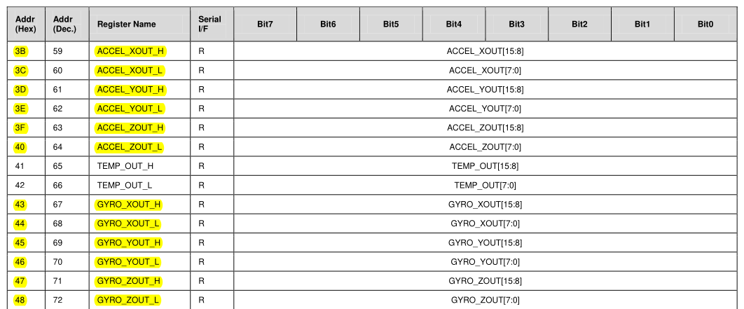
Reading the accelerometer and gyroscope data from the MPU6050 IMU is very similar to reading the temperature data with a few key differences. The first difference is that the accelerometer and gyroscope have a high and low register for each axis. This means that getting all of the data from the accelerometer and gyroscope requires reading six registers each. Below is a snapshot of the register table on the register map and descriptions datasheet that shows the registers which hold the latest accelerometer and gyroscope data.
The accelerometer and gyroscope registers on the MPU6050 IMU.
 |
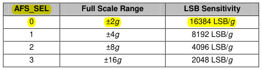
The other key difference is in the way the raw data is converted to a human readable number. The datasheet defined a clear formula for converting the temperature data from the sensor to degrees Celsius. For the accelerometer and gyroscope, the values only need to be divided by the number of LSB (least significant bits) per unit. For the accelerometer, the LSB/g (least significant bits per gravitational force) is set by the AFS_SEL bits in the ACCEL_CONFIG register. By default it is set to zero, so the values can range from -2 g to +2 g, and the sensitivity is set to 16384 LSB/g. This means that after the high and low registers for each axis of the accelerometer are combined, we need to divide that number by 16384 to get a number in g’s. If you are using this IMU in another application and expect a wider range of g’s than -2 g to +2 g, then you should change the AFS_SEL bit in the ACCEL_CONFIG register according to the table below.
Range and sensitivity table for the accelerometer.
 |
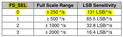
For the gyroscope, the LSB/°/s (least significant bits per degree per second) is set by the FS_SEL bits in the GYRO_CONFIG register. By default it is set to zero, so the values can range from -250 °/s to +250 °/s, and the sensitivity is 131 LSB/°/s. This means that after the high and low registers for each axis of the gyroscope are combined, we need to divide that number by 131 to get a number in °/s. In this guide, FS_SEL will be left at 0, but in outside applications you should reference this table and change the FS_SEL bit according to your application.
Range and sensitivity table for the gyroscope.
 |
Below is a script for reading and printing the gyroscope and accelerometer data off of the MPU6050 IMU. Save this code as “main.py” on your ESP8266 NodeMCU, then press the restart button to run it.
from machine import I2C, Pin
from time import sleep_ms

MPU6050_ADDR = 0x68

MPU6050_ACCEL_XOUT_H = 0x3B
MPU6050_ACCEL_XOUT_L = 0x3C
MPU6050_ACCEL_YOUT_H = 0x3D
MPU6050_ACCEL_YOUT_L = 0x3E
MPU6050_ACCEL_ZOUT_H = 0x3F
MPU6050_ACCEL_ZOUT_L = 0x40
MPU6050_GYRO_XOUT_H = 0x43
MPU6050_GYRO_XOUT_L = 0x44
MPU6050_GYRO_YOUT_H = 0x45
MPU6050_GYRO_YOUT_L = 0x46
MPU6050_GYRO_ZOUT_H = 0x47
MPU6050_GYRO_ZOUT_L = 0x48
MPU6050_PWR_MGMT_1 = 0x6B

MPU6050_LSBG = 16384.0
MPU6050_LSBDS = 131.0


def mpu6050_init(i2c):
    i2c.writeto_mem(MPU6050_ADDR, MPU6050_PWR_MGMT_1, bytes([0]))


def combine_register_values(h, l):
    if not h[0] & 0x80:
        return h[0] << 8 | l[0]
    return -((h[0] ^ 255) << 8) |  (l[0] ^ 255) + 1


def mpu6050_get_accel(i2c):
    accel_x_h = i2c.readfrom_mem(MPU6050_ADDR, MPU6050_ACCEL_XOUT_H, 1)
    accel_x_l = i2c.readfrom_mem(MPU6050_ADDR, MPU6050_ACCEL_XOUT_L, 1)
    accel_y_h = i2c.readfrom_mem(MPU6050_ADDR, MPU6050_ACCEL_YOUT_H, 1)
    accel_y_l = i2c.readfrom_mem(MPU6050_ADDR, MPU6050_ACCEL_YOUT_L, 1)
    accel_z_h = i2c.readfrom_mem(MPU6050_ADDR, MPU6050_ACCEL_ZOUT_H, 1)
    accel_z_l = i2c.readfrom_mem(MPU6050_ADDR, MPU6050_ACCEL_ZOUT_L, 1)

    return [combine_register_values(accel_x_h, accel_x_l) / MPU6050_LSBG,
            combine_register_values(accel_y_h, accel_y_l) / MPU6050_LSBG,
            combine_register_values(accel_z_h, accel_z_l) / MPU6050_LSBG]


def mpu6050_get_gyro(i2c):
    gyro_x_h = i2c.readfrom_mem(MPU6050_ADDR, MPU6050_GYRO_XOUT_H, 1)
    gyro_x_l = i2c.readfrom_mem(MPU6050_ADDR, MPU6050_GYRO_XOUT_L, 1)
    gyro_y_h = i2c.readfrom_mem(MPU6050_ADDR, MPU6050_GYRO_YOUT_H, 1)
    gyro_y_l = i2c.readfrom_mem(MPU6050_ADDR, MPU6050_GYRO_YOUT_L, 1)
    gyro_z_h = i2c.readfrom_mem(MPU6050_ADDR, MPU6050_GYRO_ZOUT_H, 1)
    gyro_z_l = i2c.readfrom_mem(MPU6050_ADDR, MPU6050_GYRO_ZOUT_L, 1)

    return [combine_register_values(gyro_x_h, gyro_x_l) / MPU6050_LSBDS,
            combine_register_values(gyro_y_h, gyro_y_l) / MPU6050_LSBDS,
            combine_register_values(gyro_z_h, gyro_z_l) / MPU6050_LSBDS]


if __name__ == "__main__":
    i2c = I2C(scl=Pin(5), sda=Pin(4))
    mpu6050_init(i2c)

    while True:
        print("Accelerometer:\t", mpu6050_get_accel(i2c), "g")
        print("Gyroscope:\t", mpu6050_get_gyro(i2c), "°/s")
        sleep_ms(500)
Full MPU6050 IMU Code
Below is the code for reading and printing the temperature, acceleration, and gyroscope data from the MPU6050 IMU. Save this code as “main.py” on your ESP8266 NodeMCU, then press the restart button to run it.
from machine import I2C, Pin
from time import sleep_ms

MPU6050_ADDR = 0x68

MPU6050_ACCEL_XOUT_H = 0x3B
MPU6050_ACCEL_XOUT_L = 0x3C
MPU6050_ACCEL_YOUT_H = 0x3D
MPU6050_ACCEL_YOUT_L = 0x3E
MPU6050_ACCEL_ZOUT_H = 0x3F
MPU6050_ACCEL_ZOUT_L = 0x40
MPU6050_TEMP_OUT_H = 0x41
MPU6050_TEMP_OUT_L = 0x42
MPU6050_GYRO_XOUT_H = 0x43
MPU6050_GYRO_XOUT_L = 0x44
MPU6050_GYRO_YOUT_H = 0x45
MPU6050_GYRO_YOUT_L = 0x46
MPU6050_GYRO_ZOUT_H = 0x47
MPU6050_GYRO_ZOUT_L = 0x48
MPU6050_PWR_MGMT_1 = 0x6B

MPU6050_LSBC = 340.0
MPU6050_TEMP_OFFSET = 36.53
MPU6050_LSBG = 16384.0
MPU6050_LSBDS = 131.0


def mpu6050_init(i2c):
    i2c.writeto_mem(MPU6050_ADDR, MPU6050_PWR_MGMT_1, bytes([0]))


def combine_register_values(h, l):
    if not h[0] & 0x80:
        return h[0] << 8 | l[0]
    return -((h[0] ^ 255) << 8) |  (l[0] ^ 255) + 1


def mpu6050_get_temp(i2c):
    temp_h = i2c.readfrom_mem(MPU6050_ADDR, MPU6050_TEMP_OUT_H, 1)
    temp_l = i2c.readfrom_mem(MPU6050_ADDR, MPU6050_TEMP_OUT_L, 1)

    return (combine_register_values(temp_h, temp_l) / MPU6050_LSBC) + MPU6050_TEMP_OFFSET


def mpu6050_get_accel(i2c):
    accel_x_h = i2c.readfrom_mem(MPU6050_ADDR, MPU6050_ACCEL_XOUT_H, 1)
    accel_x_l = i2c.readfrom_mem(MPU6050_ADDR, MPU6050_ACCEL_XOUT_L, 1)
    accel_y_h = i2c.readfrom_mem(MPU6050_ADDR, MPU6050_ACCEL_YOUT_H, 1)
    accel_y_l = i2c.readfrom_mem(MPU6050_ADDR, MPU6050_ACCEL_YOUT_L, 1)
    accel_z_h = i2c.readfrom_mem(MPU6050_ADDR, MPU6050_ACCEL_ZOUT_H, 1)
    accel_z_l = i2c.readfrom_mem(MPU6050_ADDR, MPU6050_ACCEL_ZOUT_L, 1)

    return [combine_register_values(accel_x_h, accel_x_l) / MPU6050_LSBG,
            combine_register_values(accel_y_h, accel_y_l) / MPU6050_LSBG,
            combine_register_values(accel_z_h, accel_z_l) / MPU6050_LSBG]


def mpu6050_get_gyro(i2c):
    gyro_x_h = i2c.readfrom_mem(MPU6050_ADDR, MPU6050_GYRO_XOUT_H, 1)
    gyro_x_l = i2c.readfrom_mem(MPU6050_ADDR, MPU6050_GYRO_XOUT_L, 1)
    gyro_y_h = i2c.readfrom_mem(MPU6050_ADDR, MPU6050_GYRO_YOUT_H, 1)
    gyro_y_l = i2c.readfrom_mem(MPU6050_ADDR, MPU6050_GYRO_YOUT_L, 1)
    gyro_z_h = i2c.readfrom_mem(MPU6050_ADDR, MPU6050_GYRO_ZOUT_H, 1)
    gyro_z_l = i2c.readfrom_mem(MPU6050_ADDR, MPU6050_GYRO_ZOUT_L, 1)

    return [combine_register_values(gyro_x_h, gyro_x_l) / MPU6050_LSBDS,
            combine_register_values(gyro_y_h, gyro_y_l) / MPU6050_LSBDS,
            combine_register_values(gyro_z_h, gyro_z_l) / MPU6050_LSBDS]


if __name__ == "__main__":
    i2c = I2C(scl=Pin(5), sda=Pin(4))
    mpu6050_init(i2c)

    while True:
        print("Temperature:\t", mpu6050_get_temp(i2c), "°C")
        print("Accelerometer:\t", mpu6050_get_accel(i2c), "g")
        print("Gyroscope:\t", mpu6050_get_gyro(i2c), "°/s")
        sleep_ms(500)
Using the Interrupt Pin
In the setup section of this guide, the INT pin on the MPU6050 was connected to GPIO14 (D5) of the ESP8266 NodeMCU. The INT pin sends a signal when a configurable condition is met. Let’s configure the IMU to send an interrupt signal when there is new data ready to be read. According to the register map and descriptions datasheet, bit 0 needs to be enabled in the INT_ENABLE register to get an interrupt signal when data is ready.
INT_ENABLE register in section 4.15 of the register map and descriptions datasheet.
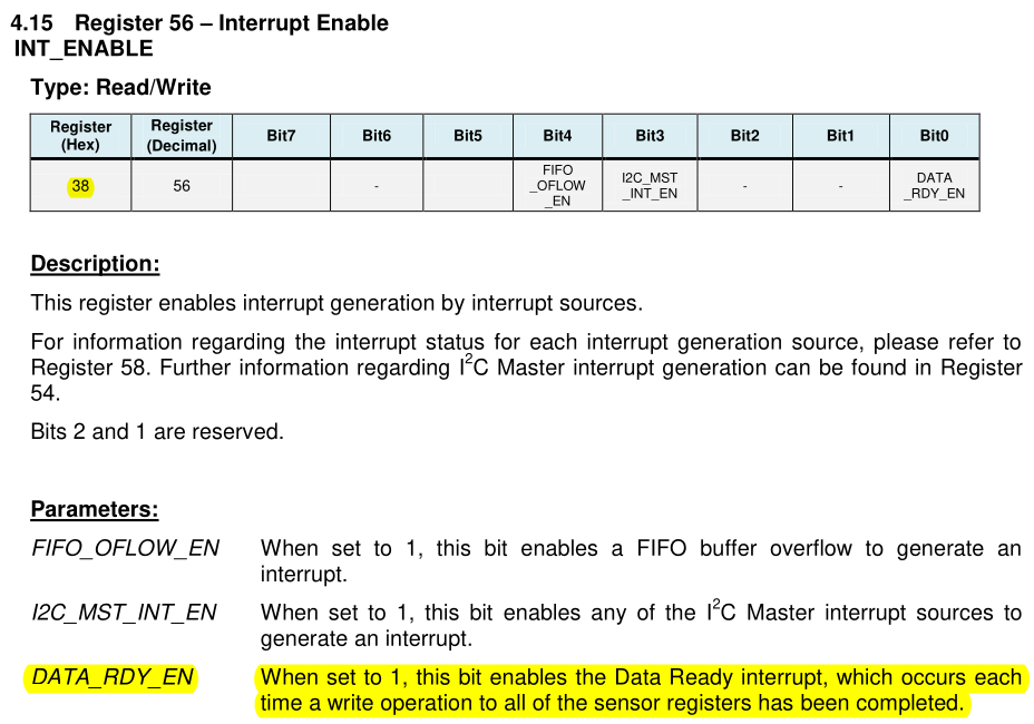 |
The following code does the same as the last script, except for that instead of reading and printing data every 500 ms, the data is read and printed as soon as the DATA_RDY_EN signal is recieved from the INT pin. Save this code as “main.py” on your ESP8266 NodeMCU, then press the restart button to run it.
from machine import I2C, Pin
from time import sleep_ms

MPU6050_ADDR = 0x68

MPU6050_INT_ENABLE = 0x38
MPU6050_ACCEL_XOUT_H = 0x3B
MPU6050_ACCEL_XOUT_L = 0x3C
MPU6050_ACCEL_YOUT_H = 0x3D
MPU6050_ACCEL_YOUT_L = 0x3E
MPU6050_ACCEL_ZOUT_H = 0x3F
MPU6050_ACCEL_ZOUT_L = 0x40
MPU6050_TEMP_OUT_H = 0x41
MPU6050_TEMP_OUT_L = 0x42
MPU6050_GYRO_XOUT_H = 0x43
MPU6050_GYRO_XOUT_L = 0x44
MPU6050_GYRO_YOUT_H = 0x45
MPU6050_GYRO_YOUT_L = 0x46
MPU6050_GYRO_ZOUT_H = 0x47
MPU6050_GYRO_ZOUT_L = 0x48
MPU6050_PWR_MGMT_1 = 0x6B

MPU6050_LSBC = 340.0
MPU6050_TEMP_OFFSET = 36.53
MPU6050_LSBG = 16384.0
MPU6050_LSBDS = 131.0


def mpu6050_init(i2c):
    i2c.writeto_mem(MPU6050_ADDR, MPU6050_PWR_MGMT_1, bytes([0])) # disable sleep
    i2c.writeto_mem(MPU6050_ADDR, MPU6050_INT_ENABLE, bytes([1])) # enable interrupt on data ready (DATA_READ_EN)


def combine_register_values(h, l):
    if not h[0] & 0x80:
        return h[0] << 8 | l[0]
    return -((h[0] ^ 255) << 8) |  (l[0] ^ 255) + 1


def mpu6050_get_temp(i2c):
    temp_h = i2c.readfrom_mem(MPU6050_ADDR, MPU6050_TEMP_OUT_H, 1)
    temp_l = i2c.readfrom_mem(MPU6050_ADDR, MPU6050_TEMP_OUT_L, 1)

    return (combine_register_values(temp_h, temp_l) / MPU6050_LSBC) + MPU6050_TEMP_OFFSET


def mpu6050_get_accel(i2c):
    accel_x_h = i2c.readfrom_mem(MPU6050_ADDR, MPU6050_ACCEL_XOUT_H, 1)
    accel_x_l = i2c.readfrom_mem(MPU6050_ADDR, MPU6050_ACCEL_XOUT_L, 1)
    accel_y_h = i2c.readfrom_mem(MPU6050_ADDR, MPU6050_ACCEL_YOUT_H, 1)
    accel_y_l = i2c.readfrom_mem(MPU6050_ADDR, MPU6050_ACCEL_YOUT_L, 1)
    accel_z_h = i2c.readfrom_mem(MPU6050_ADDR, MPU6050_ACCEL_ZOUT_H, 1)
    accel_z_l = i2c.readfrom_mem(MPU6050_ADDR, MPU6050_ACCEL_ZOUT_L, 1)

    return [combine_register_values(accel_x_h, accel_x_l) / MPU6050_LSBG,
            combine_register_values(accel_y_h, accel_y_l) / MPU6050_LSBG,
            combine_register_values(accel_z_h, accel_z_l) / MPU6050_LSBG]


def mpu6050_get_gyro(i2c):
    gyro_x_h = i2c.readfrom_mem(MPU6050_ADDR, MPU6050_GYRO_XOUT_H, 1)
    gyro_x_l = i2c.readfrom_mem(MPU6050_ADDR, MPU6050_GYRO_XOUT_L, 1)
    gyro_y_h = i2c.readfrom_mem(MPU6050_ADDR, MPU6050_GYRO_YOUT_H, 1)
    gyro_y_l = i2c.readfrom_mem(MPU6050_ADDR, MPU6050_GYRO_YOUT_L, 1)
    gyro_z_h = i2c.readfrom_mem(MPU6050_ADDR, MPU6050_GYRO_ZOUT_H, 1)
    gyro_z_l = i2c.readfrom_mem(MPU6050_ADDR, MPU6050_GYRO_ZOUT_L, 1)

    return [combine_register_values(gyro_x_h, gyro_x_l) / MPU6050_LSBDS,
            combine_register_values(gyro_y_h, gyro_y_l) / MPU6050_LSBDS,
            combine_register_values(gyro_z_h, gyro_z_l) / MPU6050_LSBDS]


def print_data(pin):
    print("Temperature:\t", mpu6050_get_temp(i2c), "°C")
    print("Accelerometer:\t", mpu6050_get_accel(i2c), "g")
    print("Gyroscope:\t", mpu6050_get_gyro(i2c), "°/s")


if __name__ == "__main__":
    i2c = I2C(scl=Pin(5), sda=Pin(4))
    mpu6050_init(i2c)

    mpu6050_int = Pin(14, Pin.IN, Pin.PULL_UP)
    mpu6050_int.irq(trigger=Pin.IRQ_FALLING, handler=print_data)
If you ran the script, you can probably tell that the data from the IMU is now being printed way to fast to be readable by a person. However, in a more typical application where IMU data is being used to control other parts of an autonomous system, getting new data as soon as possible is ideal.
MPU6050 IMU Conclusion
As you can probably tell by reading the datasheet, there are a lot of registers that weren’t used in this guide. If you interested in learning more about this particular sensor, you should take a closer look at the datasheets to see what else this sensor is capable of.
Communicating with the SSD1306 Display
To communicate with the MPU6050 IMU, the built-in I2C library that comes packaged MicroPython was used to send read and write commands to the device. However, some devices are common enough that the MicroPython developers included libraries for them with MicroPython itself. One of these devices is the SSD1306 display. This section will use this library, called ssd1306.py, to communicate with the OLED display.
Before continuing, remove the jumper wire connecting the INT pin on the MPU6050 IMU with GPIO14 (D5) on the NodeMCU. Then, press the stop button at the top of Thonny to get an open REPL.
Filling the Display
In this section follow along by entering the lines of code in the Thonny REPL. First, import SSD1306_I2C from the ssd1306 library and import I2C and Pin from machine.
>>> from ssd1306 import SSD1306_I2C
>>> from machine import I2C, Pin
Next, declare an I2C bus using the same SCL and SDA pins as before.
>>> i2c = I2C(scl=Pin(5), sda=Pin(4))
Next, a SSD1306_I2C object must be declared. For parameters, it requires the dimensions of the display and an I2C object.
>>> display = SSD1306_I2C(128, 64, i2c)
Each of the parameters in the SSD1306_I2C object declaration are itemized below for clarity:
- The first parameter is the x dimension of the display.
- The second parameter is the y dimension of the display.
- The third parameter is an
I2C object.
Now that a SSD1306_I2C object is declared, pixels can be written to the display. To tell the display to turn all of its pixels on or off, the SSD1306_I2C.fill function can be used. Providing the function a parameter of 1 tells the display to turn all pixels on, and providing the function a parameter of 0 tells the display to turn all pixels off. After designating the state of the display, the SSD1306.show command can be called to show the display as it was told to appear.
>>> display.fill(1) # turn all pixels on
>>> display.show()
>>> display.fill(0) # turn all pixels off
>>> display.show()
What is Going on Here?
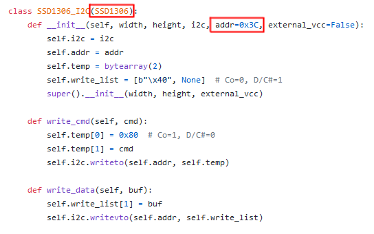
You may remember that when using the MPU6050 IMU, that a slave device address was needed in order to communicate with it over I2C. In the section above, we were able to call the fill and show commands on the display using I2C and it responded accordingly. So, how is this possible without use of the SSD1306’s slave device address? The answer is through use of the ssd1306 library that we imported. In the init function of the SSD1306_I2C class declaration there is a parameter called addr that is set to 0x3C by default. This address matches the address that was found when calling the I2C.scan function earlier in this guide. This addr variable can be used throughout the class to reference the slave device address of the SSD1306 display.
The SSD1306_I2C class in the MicroPython source code.
 |
If you look at the SSD1306_I2C class in the ssd1306 library source code, you will notice that there doesn’t appear to be any functions called fill or show. These functions are not located in this class, because they are inherited. On the first line of the class declaration for SSD1306_I2C, in the parentheses, is SSD1306. This syntax indicates that SSD1306_I2C inherits from SSD1306.
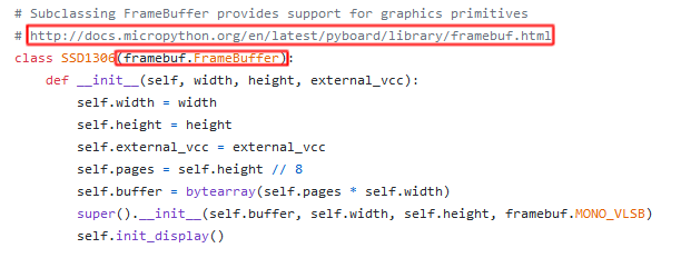
The SSD1306 class is located directly above the SSD1306_I2C class in the same file. The show function is located in this class, but the fill function is still nowhere to be found. If you look at the class declaration for SSD1306, you will see that it inherits from something called FrameBuffer and there is a link to the FrameBuffer documentation directly above the class. Following this link will bring you to a documentation page for FrameBuffer which contains the fill function along with other functions for drawing pixels, lines, rectangles, and even writing text.
The SSD1306_I2C class in the MicroPython source code.
 |
Writing Text to the Display
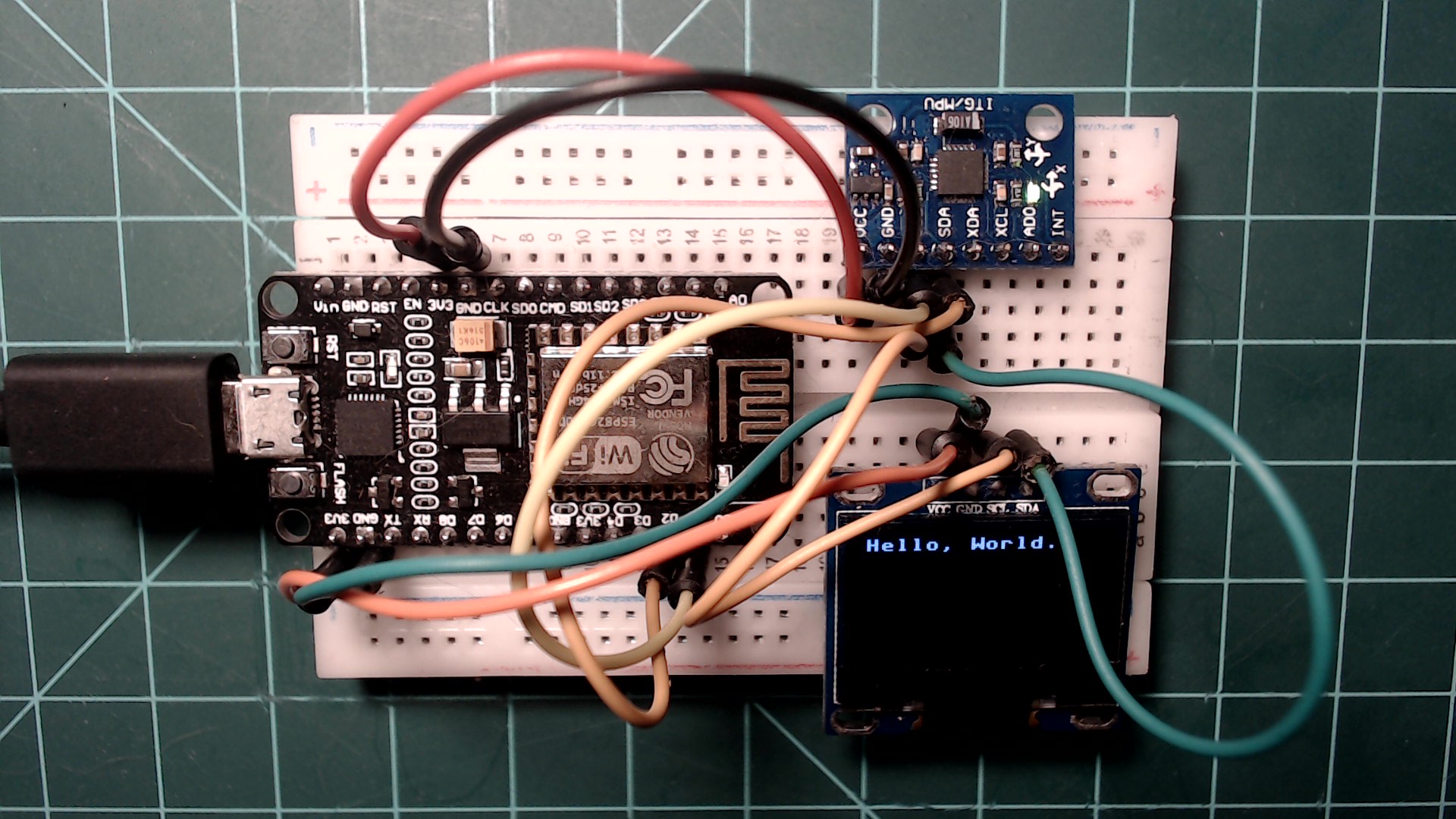
Let’s write some text to the display using the SSD1306.text function.
>>> display.text("Hello, World.", 0, 0)
>>> display.show()
Display showing text using the ssd1306 library.
 |
Each of the parameters in the SSD1306_I2C.text function are itemized below for clarity:
- The first parameter is the text to show.
- The second parameter is a x position coordinate on the display.
- The third parameter is a y position coordinate on the display.
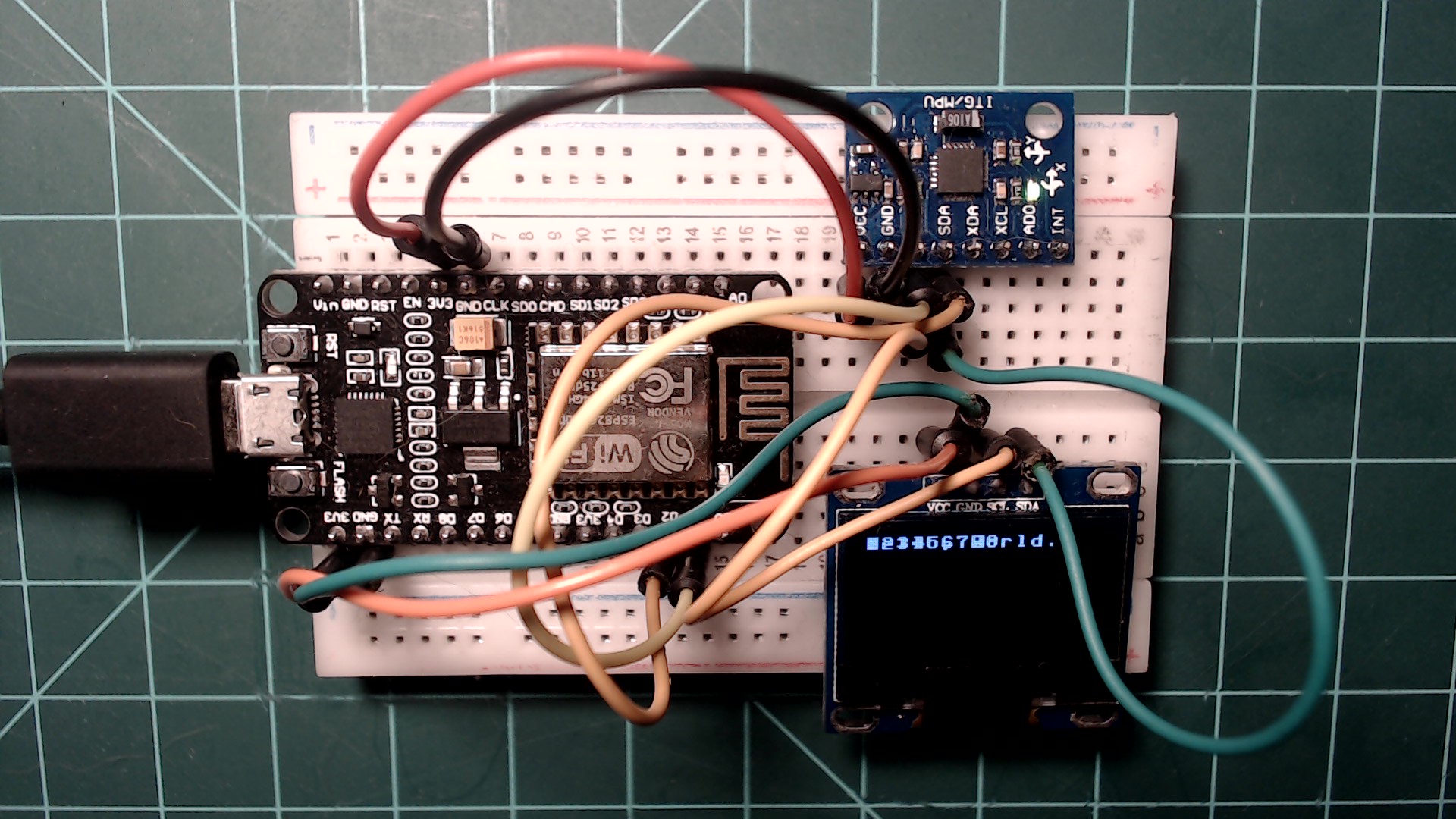
It is important to be aware of the display’s behavior when writing to it multiple times in the same program. For example, lets display different text at the same coordinates as before.
>>> display.text("123456789", 0, 0)
>>> display.show()
Your display should look like the one in the image below.
Overlapping text on the display.
 |
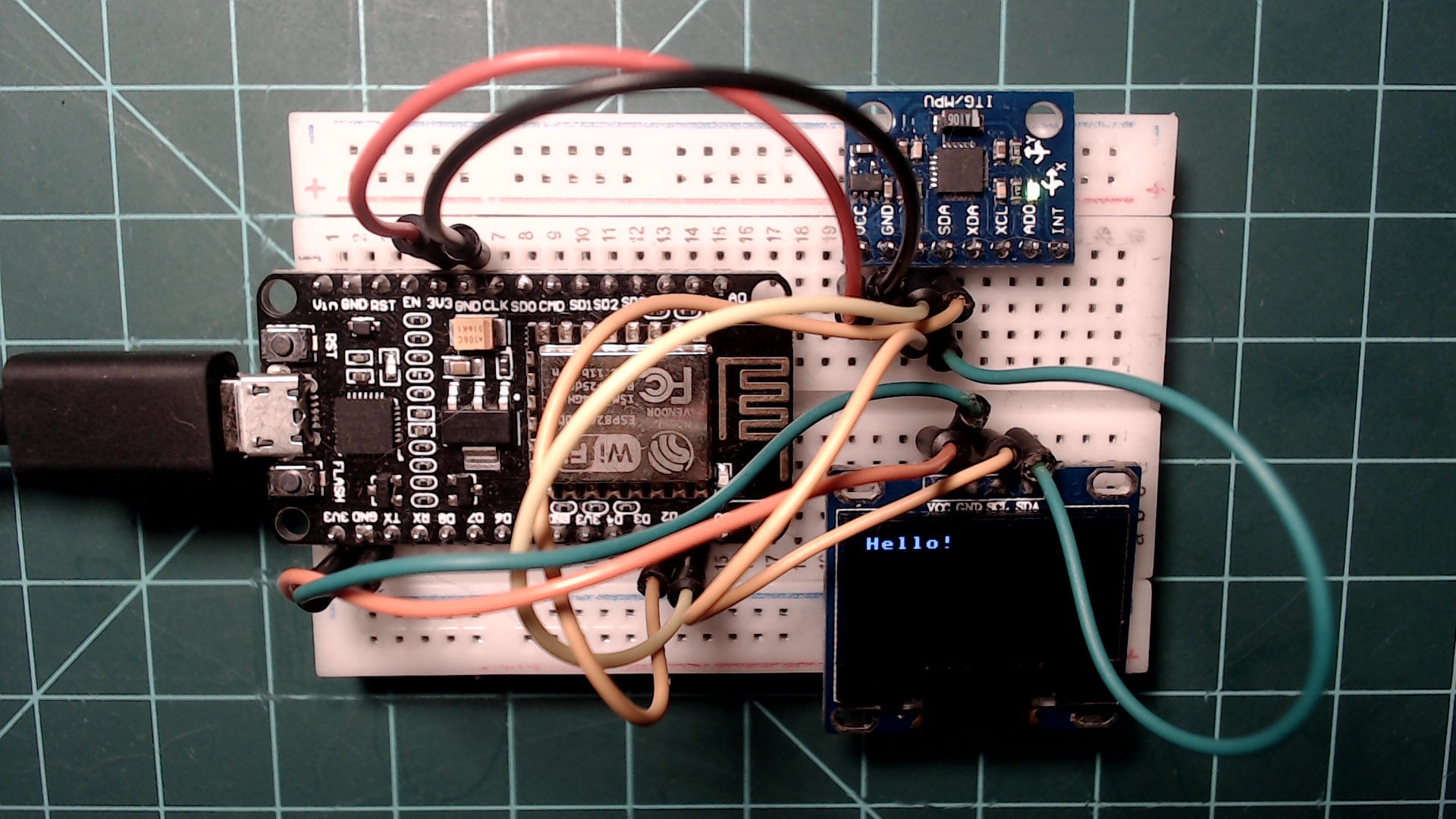
As you can see, the new text was just written on top of the old text. To avoid this issue, the display can just be cleared using the SSD1306.fill function.
>>> display.fill(0)
>>> display.text("Hello!", 0, 0)
>>> display.show()
Clearing the display allows text to show properly.
 |
Putting it All Together
You have now learned how to read data from the MPU6050 IMU and how to display data on the SSD1306 display using MicroPython. Try to put everything you have learned in this guide together on your own in the following exercises.
Exercise 1
Use everything you have learned in this guide to write a program that does the following:
- Every 500 milliseconds read the latest data from the MPU6050 IMU.
- Immediately display the latest data from the IMU on the SSD1306 display.
- No use of the INT pin or interrupts is necessary.
Below is a gif demonstrating the program. Good luck!
Demonstration of the result of excersise 1.
 |
Click here to view a solution.
from machine import I2C, Pin
from ssd1306 import SSD1306_I2C
from time import sleep_ms

DISPLAY_X = 128
DISPLAY_Y = 64

MPU6050_ADDR = 0x68

MPU6050_INT_ENABLE = 0x38
MPU6050_ACCEL_XOUT_H = 0x3B
MPU6050_ACCEL_XOUT_L = 0x3C
MPU6050_ACCEL_YOUT_H = 0x3D
MPU6050_ACCEL_YOUT_L = 0x3E
MPU6050_ACCEL_ZOUT_H = 0x3F
MPU6050_ACCEL_ZOUT_L = 0x40
MPU6050_TEMP_OUT_H = 0x41
MPU6050_TEMP_OUT_L = 0x42
MPU6050_GYRO_XOUT_H = 0x43
MPU6050_GYRO_XOUT_L = 0x44
MPU6050_GYRO_YOUT_H = 0x45
MPU6050_GYRO_YOUT_L = 0x46
MPU6050_GYRO_ZOUT_H = 0x47
MPU6050_GYRO_ZOUT_L = 0x48
MPU6050_PWR_MGMT_1 = 0x6B

MPU6050_LSBC = 340.0
MPU6050_TEMP_OFFSET = 36.53
MPU6050_LSBG = 16384.0
MPU6050_LSBDS = 131.0


def mpu6050_init(i2c):
    i2c.writeto_mem(MPU6050_ADDR, MPU6050_PWR_MGMT_1, bytes([0])) # disable sleep


def combine_register_values(h, l):
    if not h[0] & 0x80:
        return h[0] << 8 | l[0]
    return -((h[0] ^ 255) << 8) |  (l[0] ^ 255) + 1


def mpu6050_get_temp(i2c):
    temp_h = i2c.readfrom_mem(MPU6050_ADDR, MPU6050_TEMP_OUT_H, 1)
    temp_l = i2c.readfrom_mem(MPU6050_ADDR, MPU6050_TEMP_OUT_L, 1)

    return (combine_register_values(temp_h, temp_l) / MPU6050_LSBC) + MPU6050_TEMP_OFFSET


def mpu6050_get_accel(i2c):
    accel_x_h = i2c.readfrom_mem(MPU6050_ADDR, MPU6050_ACCEL_XOUT_H, 1)
    accel_x_l = i2c.readfrom_mem(MPU6050_ADDR, MPU6050_ACCEL_XOUT_L, 1)
    accel_y_h = i2c.readfrom_mem(MPU6050_ADDR, MPU6050_ACCEL_YOUT_H, 1)
    accel_y_l = i2c.readfrom_mem(MPU6050_ADDR, MPU6050_ACCEL_YOUT_L, 1)
    accel_z_h = i2c.readfrom_mem(MPU6050_ADDR, MPU6050_ACCEL_ZOUT_H, 1)
    accel_z_l = i2c.readfrom_mem(MPU6050_ADDR, MPU6050_ACCEL_ZOUT_L, 1)

    return [combine_register_values(accel_x_h, accel_x_l) / MPU6050_LSBG,
            combine_register_values(accel_y_h, accel_y_l) / MPU6050_LSBG,
            combine_register_values(accel_z_h, accel_z_l) / MPU6050_LSBG]


def mpu6050_get_gyro(i2c):
    gyro_x_h = i2c.readfrom_mem(MPU6050_ADDR, MPU6050_GYRO_XOUT_H, 1)
    gyro_x_l = i2c.readfrom_mem(MPU6050_ADDR, MPU6050_GYRO_XOUT_L, 1)
    gyro_y_h = i2c.readfrom_mem(MPU6050_ADDR, MPU6050_GYRO_YOUT_H, 1)
    gyro_y_l = i2c.readfrom_mem(MPU6050_ADDR, MPU6050_GYRO_YOUT_L, 1)
    gyro_z_h = i2c.readfrom_mem(MPU6050_ADDR, MPU6050_GYRO_ZOUT_H, 1)
    gyro_z_l = i2c.readfrom_mem(MPU6050_ADDR, MPU6050_GYRO_ZOUT_L, 1)

    return [combine_register_values(gyro_x_h, gyro_x_l) / MPU6050_LSBDS,
            combine_register_values(gyro_y_h, gyro_y_l) / MPU6050_LSBDS,
            combine_register_values(gyro_z_h, gyro_z_l) / MPU6050_LSBDS]


def display_imu_data(i2c, display):
    accel_data = mpu6050_get_accel(i2c)
    gyro_data = mpu6050_get_gyro(i2c)


    display.fill(0)

    display.text("accel_x: ", 0, 0)
    display.text("accel_y: ", 0, 8)
    display.text("accel_z: ", 0, 16)
    display.text("gyro_x: ", 0, 24)
    display.text("gyro_y: ", 0, 32)
    display.text("gyro_z: ", 0, 40)
    display.text("temp: ", 0, 48)

    display.text(str(accel_data[0]), 64, 0)
    display.text(str(accel_data[1]), 64, 8)
    display.text(str(accel_data[2]), 64, 16)
    display.text(str(gyro_data[0]), 64, 24)
    display.text(str(gyro_data[1]), 64, 32)
    display.text(str(gyro_data[2]), 64, 40)
    display.text(str(mpu6050_get_temp(i2c)), 64, 48)

    display.show()


if __name__ == "__main__":
    i2c = I2C(scl=Pin(5), sda=Pin(4))
    mpu6050_init(i2c)
    display = SSD1306_I2C(DISPLAY_X, DISPLAY_Y, i2c)

    while True:
        display_imu_data(i2c, display)
        sleep_ms(500)
Exercise 2
As a second excersise, try editing the solution from the previous excersise to reduce the number of I2C.readfrom_mem calls you make. For example, when getting the temperature data from the MPU6050 IMU you are probably making two calls that are each reading one byte.
temp_h = i2c.readfrom_mem(0x68, 0x41, 1)
temp_l = i2c.readfrom_mem(0x68, 0x42, 1)
Recall that the third parameter in this function is the number of bytes to be read. Since the data that we are reading is in sequential order in memory (0x41 followed by 0x42), both of these memory addresses can be read by starting at memory address 0x41 and reading 2 bytes.
temp_data = i2c.readfrom_mem(0x68, 0x41, 2)
Change the previous solution so that all of the MPU6050 IMU data is read 2 bytes at time. It should function exactly the same as previously.
Click here to view a solution.
from machine import I2C, Pin
from ssd1306 import SSD1306_I2C
from time import sleep_ms

DISPLAY_X = 128
DISPLAY_Y = 64

MPU6050_ADDR = 0x68

MPU6050_INT_ENABLE = 0x38
MPU6050_ACCEL_XOUT_H = 0x3B
MPU6050_ACCEL_XOUT_L = 0x3C
MPU6050_ACCEL_YOUT_H = 0x3D
MPU6050_ACCEL_YOUT_L = 0x3E
MPU6050_ACCEL_ZOUT_H = 0x3F
MPU6050_ACCEL_ZOUT_L = 0x40
MPU6050_TEMP_OUT_H = 0x41
MPU6050_TEMP_OUT_L = 0x42
MPU6050_GYRO_XOUT_H = 0x43
MPU6050_GYRO_XOUT_L = 0x44
MPU6050_GYRO_YOUT_H = 0x45
MPU6050_GYRO_YOUT_L = 0x46
MPU6050_GYRO_ZOUT_H = 0x47
MPU6050_GYRO_ZOUT_L = 0x48
MPU6050_PWR_MGMT_1 = 0x6B

MPU6050_LSBC = 340.0
MPU6050_TEMP_OFFSET = 36.53
MPU6050_LSBG = 16384.0
MPU6050_LSBDS = 131.0


def mpu6050_init(i2c):
    i2c.writeto_mem(MPU6050_ADDR, MPU6050_PWR_MGMT_1, bytes([0])) # disable sleep


def combine_register_values(data):
    if not data[0] & 0x80:
        return data[0] << 8 | data[1]
    return -((data[0] ^ 255) << 8) |  (data[1] ^ 255) + 1


def mpu6050_get_temp(i2c):
    temp_data = i2c.readfrom_mem(MPU6050_ADDR, MPU6050_TEMP_OUT_H, 2)

    return (combine_register_values(temp_data) / MPU6050_LSBC) + MPU6050_TEMP_OFFSET


def mpu6050_get_accel(i2c):
    accel_x_data = i2c.readfrom_mem(MPU6050_ADDR, MPU6050_ACCEL_XOUT_H, 2)
    accel_y_data = i2c.readfrom_mem(MPU6050_ADDR, MPU6050_ACCEL_YOUT_H, 2)
    accel_z_data = i2c.readfrom_mem(MPU6050_ADDR, MPU6050_ACCEL_ZOUT_H, 2)

    return [combine_register_values(accel_x_data) / MPU6050_LSBG,
            combine_register_values(accel_y_data) / MPU6050_LSBG,
            combine_register_values(accel_z_data) / MPU6050_LSBG]


def mpu6050_get_gyro(i2c):
    gyro_x_data = i2c.readfrom_mem(MPU6050_ADDR, MPU6050_GYRO_XOUT_H, 2)
    gyro_y_data = i2c.readfrom_mem(MPU6050_ADDR, MPU6050_GYRO_YOUT_H, 2)
    gyro_z_data = i2c.readfrom_mem(MPU6050_ADDR, MPU6050_GYRO_ZOUT_H, 2)

    return [combine_register_values(gyro_x_data) / MPU6050_LSBDS,
            combine_register_values(gyro_y_data) / MPU6050_LSBDS,
            combine_register_values(gyro_z_data) / MPU6050_LSBDS]


def display_imu_data(i2c, display):
    accel_data = mpu6050_get_accel(i2c)
    gyro_data = mpu6050_get_gyro(i2c)


    display.fill(0)

    display.text("accel_x: ", 0, 0)
    display.text("accel_y: ", 0, 8)
    display.text("accel_z: ", 0, 16)
    display.text("gyro_x: ", 0, 24)
    display.text("gyro_y: ", 0, 32)
    display.text("gyro_z: ", 0, 40)
    display.text("temp: ", 0, 48)

    display.text(str(accel_data[0]), 64, 0)
    display.text(str(accel_data[1]), 64, 8)
    display.text(str(accel_data[2]), 64, 16)
    display.text(str(gyro_data[0]), 64, 24)
    display.text(str(gyro_data[1]), 64, 32)
    display.text(str(gyro_data[2]), 64, 40)
    display.text(str(mpu6050_get_temp(i2c)), 64, 48)

    display.show()


if __name__ == "__main__":
    i2c = I2C(scl=Pin(5), sda=Pin(4))
    mpu6050_init(i2c)
    display = SSD1306_I2C(DISPLAY_X, DISPLAY_Y, i2c)

    while True:
        display_imu_data(i2c, display)
        sleep_ms(500)
Conclusion
This concludes this guide. If you wish to learn more about I2C, try getting some other I2C modules and using their data sheets to program them. There are also many registers on the MPU6050 IMU that were not used in this guide, try taking a look at what they do on the datasheet. Lastly, this guide used a built in Python library to interface with the SSD1306 display. If you want to learn more about what was going on behind the scenes, try comparing the ssd1306.py library with the SSD1306 datasheet. Links to these resources can be found below.
Shoutout to Kevin Thomas for creating a MPU6050 driver class using knowledge from this guide. You can find the repository it here.
Stay tuned for more NodeMCU guides!
1
Afzal, Sal. “I2C Primer: What Is I2C? (Part 1).” I2C Primer: What Is I2C? (Part 1) | Analog Devices, www.analog.com/en/technical-articles/i2c-primer-what-is-i2c-part-1.html. Link
2
Derivative from MPU6050 3-Axis Acceleration + Gyroscope 6DOF - I2C Interface. www.robotics.org.za/GY-521. Link
3
SFUptownMaker. I2C. learn.sparkfun.com/tutorials/i2c/all. Link