Prerequisite Guides
Supplemental Guides
You Will Need
| ESP32 NodeMCU (38 pin) |
| MicroUSB Cable |
| Computer running Windows, Linux, or MacOSX |
| Breadboard |
| LED |
| 1kΩ - 10kΩ Resistor |
| 46Ω - 100Ω Resistor |
| 6mm Push Button |
| Jumper Wires |
Setup
If you do not have a ESP32 NodeMCU flashed with MicroPython, or do not know how to upload programs to an ESP32 NodeMCU, then I recommend reading our Getting Started with ESP32 and MicroPython guide before continuing further with this guide.
NodeMCU? ESP8266? ESP32?
In this tutorial series, terms have been thrown out like “ESP32” and “NodeMCU”. In other Micronote tutorials we use terms like “ESP8266”. What are all of these terms referring to and how do they differ?
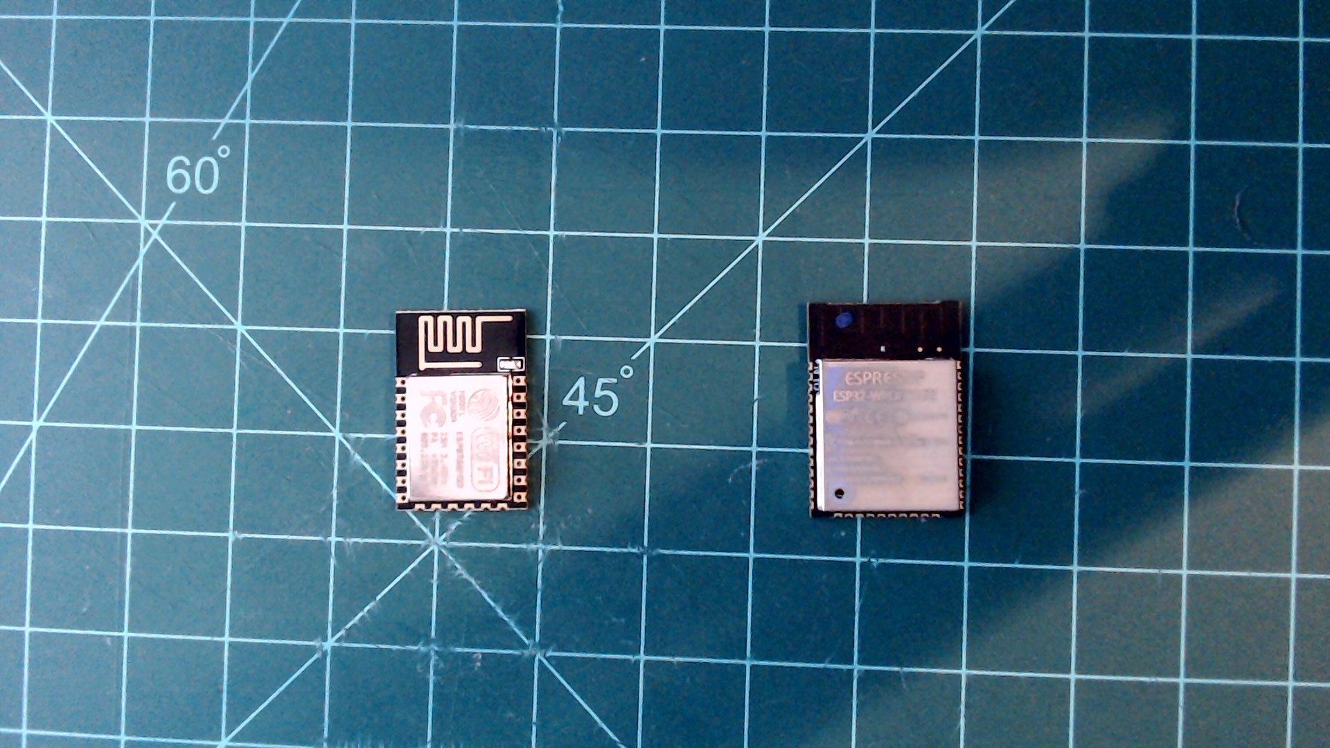
Below is an image of an ESP8266 module next to an ESP32 module. The ESP32 is the successor to the ESP8266 and it is much more powerful.
Left: ESP8266 module. Right: ESP32 module.
 |
It would be difficult to interface with these modules on their own. There is no port for charging them, and no port for programming them either.
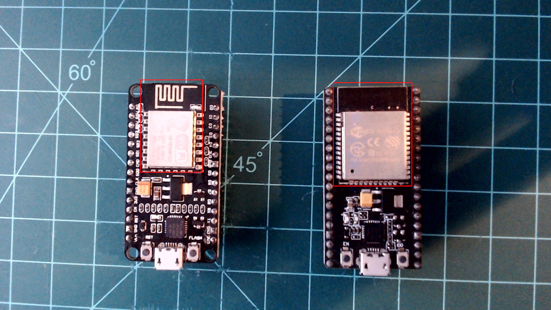
This is where the NodeMCU comes in. NodeMCUs are development boards based around the ESP8266 and ESP32 modules. They include a CP2102 USB to UART chip connected to a micoUSB port. They also have a regulator to lower the input voltage from 5V to 3.3V. This allows for the microcontrollers to be safely powered and programmed through USB.
Left: ESP8266 NodeMCU development board. Right: ESP32 NodeMCU development board.
 |
NodeMCU Pinmap
The image below is an important reference to have when working with a NodeMCU development board. For now, the only thing you need to pay attention to is the pins that are labeled GPIOX, with X being an integer (in the white boxes). With some exceptions, these pins are generally available for use. When referencing GPIO pins in MicroPython code the GPIO number is always how to indicate a pin. Disregard the text written on the development board that says “PX”. The blue shape in the middle is meant to represent the ESP32 NodeMCU viewed from the top with the usb towards the bottom of the image.
Quick reference for pin identifiers and functions.[1]
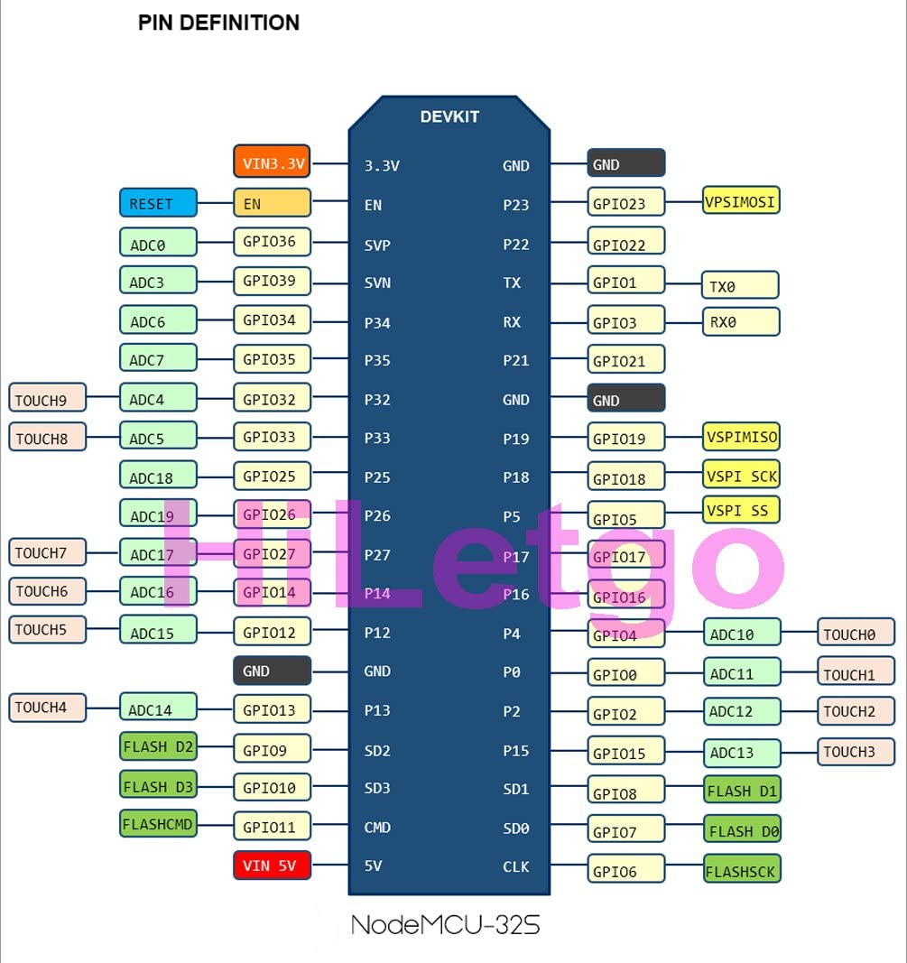 |
We will get into more detail in future guides about what the other abbreviations in the diagram mean.
Blinking a LED
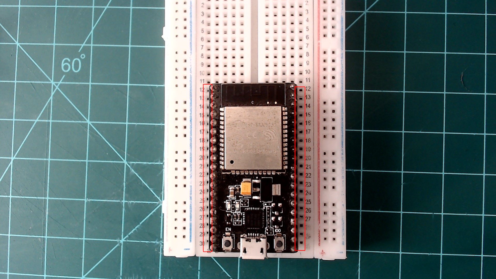
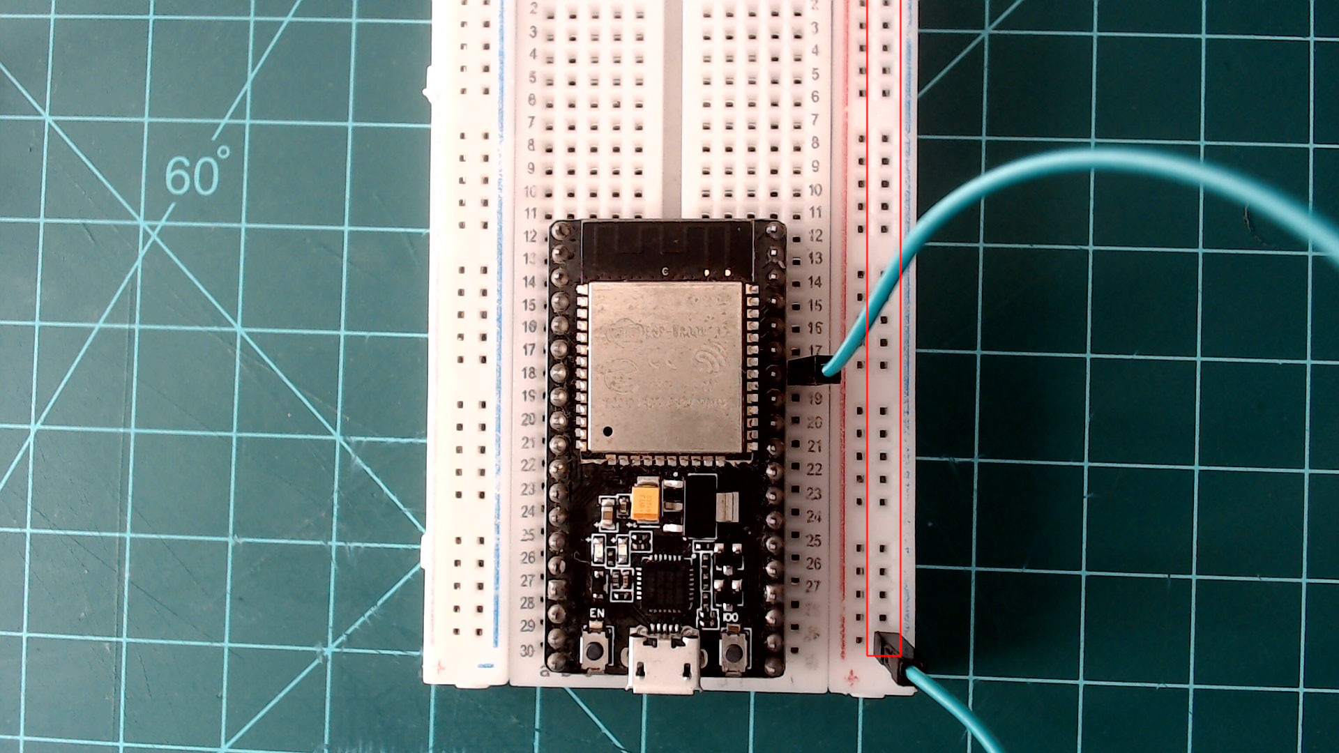
Carefully plug your NodeMCU into the breadboard. Line it up with the holes so that there is a single vertical column of holes on both sides of the board. Then, push the NodeMCU straight down into the breadboard until you can no longer see the sides of the metal pins.
Center the NodeMCU on the breadboard as seen here.
 |
There are several pins on the NodeMCU labeled as “GND”. Connect one of these pins to a nearby rail on the outside edge of the breadboard using a jumper wire. This rail is now your ground rail. My NodeMCU’s pins are labeled on the bottom side of the board. If yours is labeled similarly, you can find your pin labels on the pinout diagram above.
Create a ground rail by connecting GND to a nearby breadboard rail.
 |
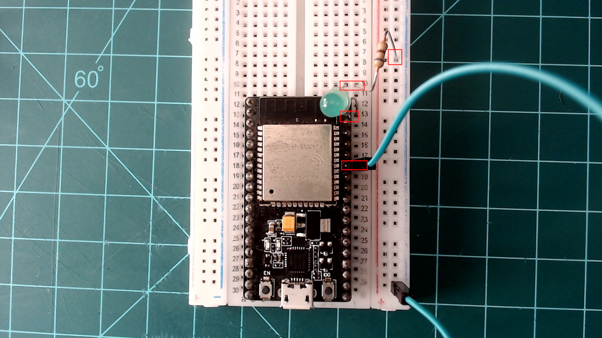
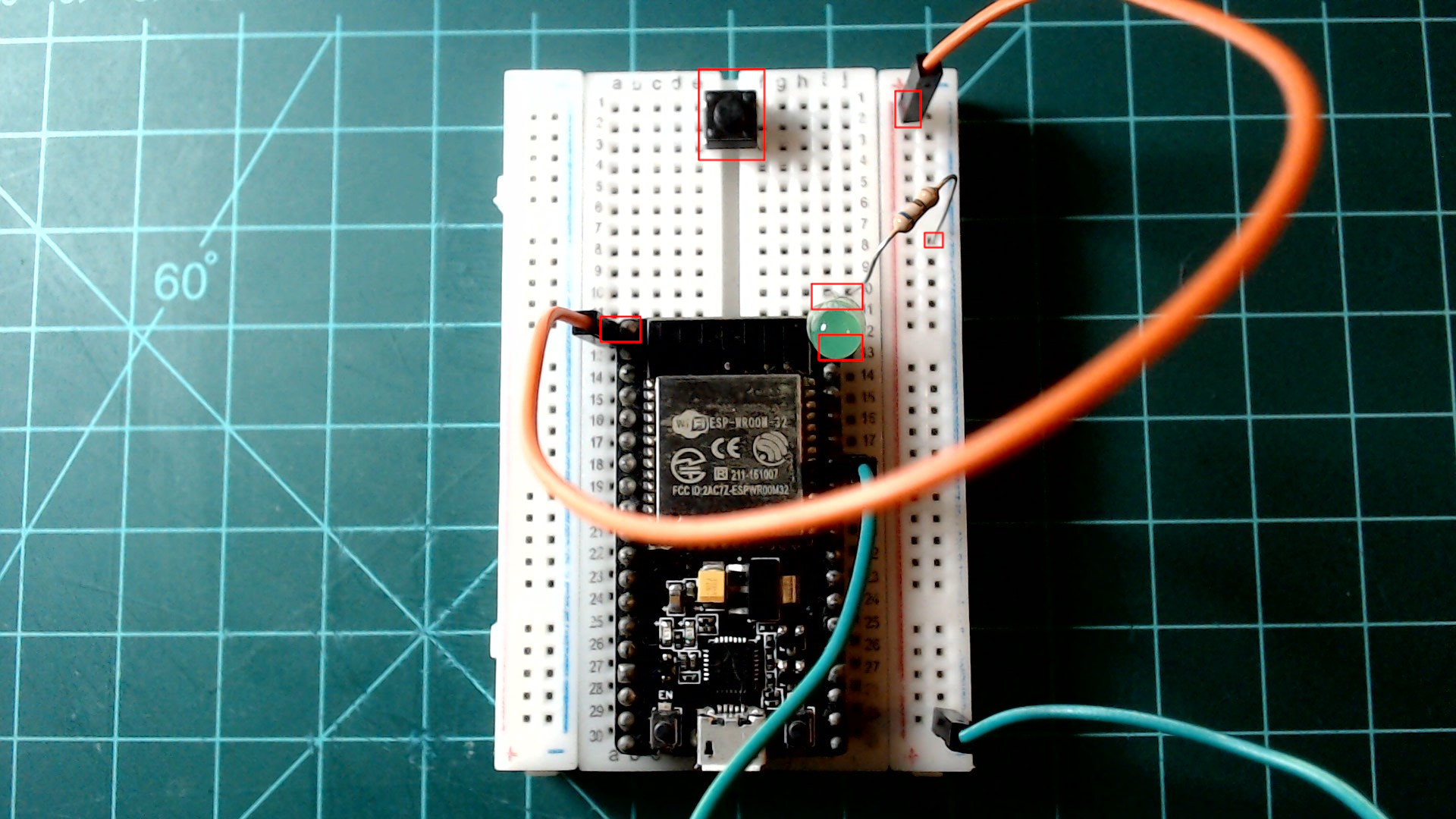
Plug the long end of your LED into the GPIO23 pin and the short end of the LED into an empty breadboard row. Next, take a resistor in the range of 46Ω - 100Ω and connect the row containing the short end of the LED to the ground rail on your breadboard.
Complete the circuit by adding the LED and resistor as shown.
 |
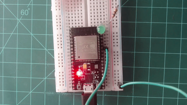
Plug the NodeMCU into your computer using a microUSB cable and launch Thonny. Make sure the interpreter and port is set, and press the stop button so that you have a REPL available in the shell tab. Enter the following code into the editor and save to “Micropython Device” as “main.py”. After saving, press the small reset button on your NodeMCU. The button on my NodeMCU is on the left and labeled as “EN”. This will reset the NodeMCU and run main.py. Your should see the LED should blink ten times.
from machine import Pin
from time import sleep

led = Pin(23, Pin.OUT)

for _ in range(10):
    led.value(1)
    sleep(1)
    led.value(0)
    sleep(1)
The output result of the blink sketch above.
 |
Before moving on in this section, make sure that the microUSB cable is unplugged from the NodeMCU. It is good practice to power down your projects when modifying them. Leave everything currently on the breadboard where it is. We will return to it in the next section.
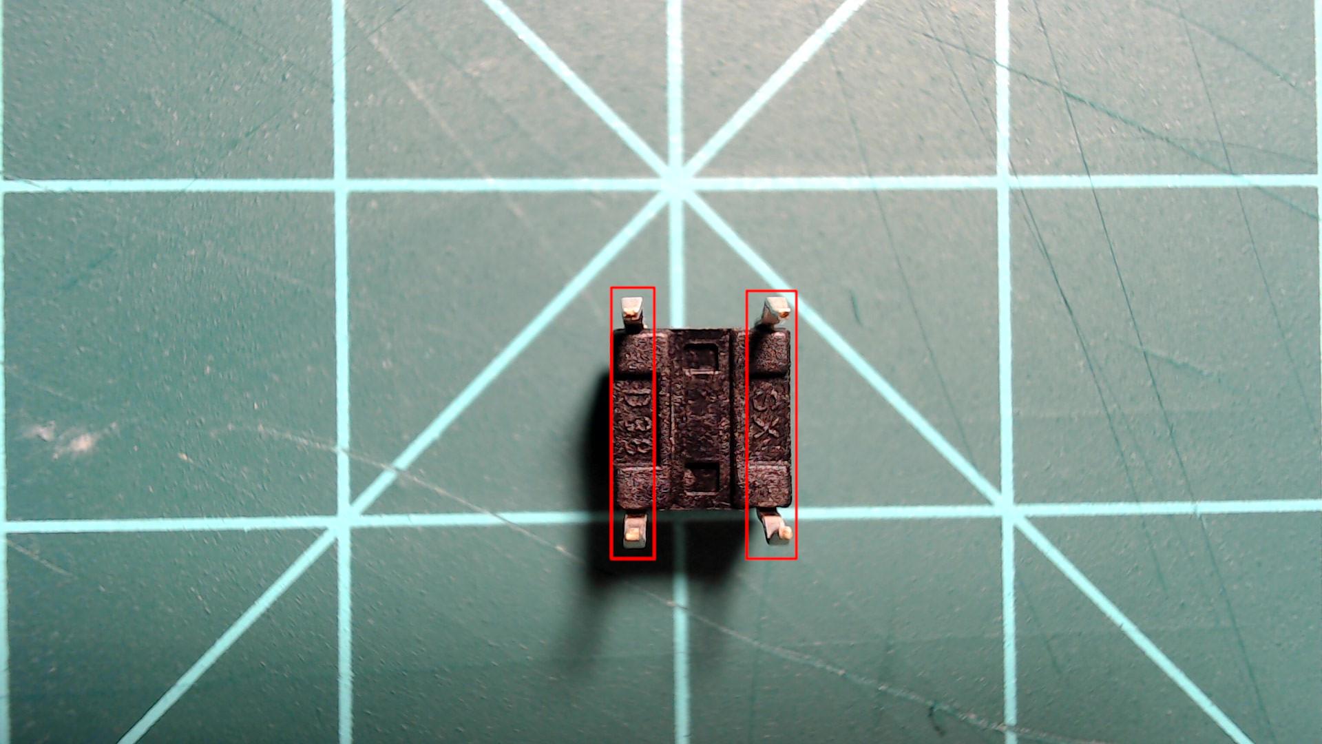
There are four leads on a pushbutton of this type, but there are only two nodes. Each node contains two leads. The image below indicates how the leads are paired. When the push button is pressed, the two nodes are connected.
When the pushbutton is pressed, the two nodes that make up the button are connected, allowing current to travel.
 |
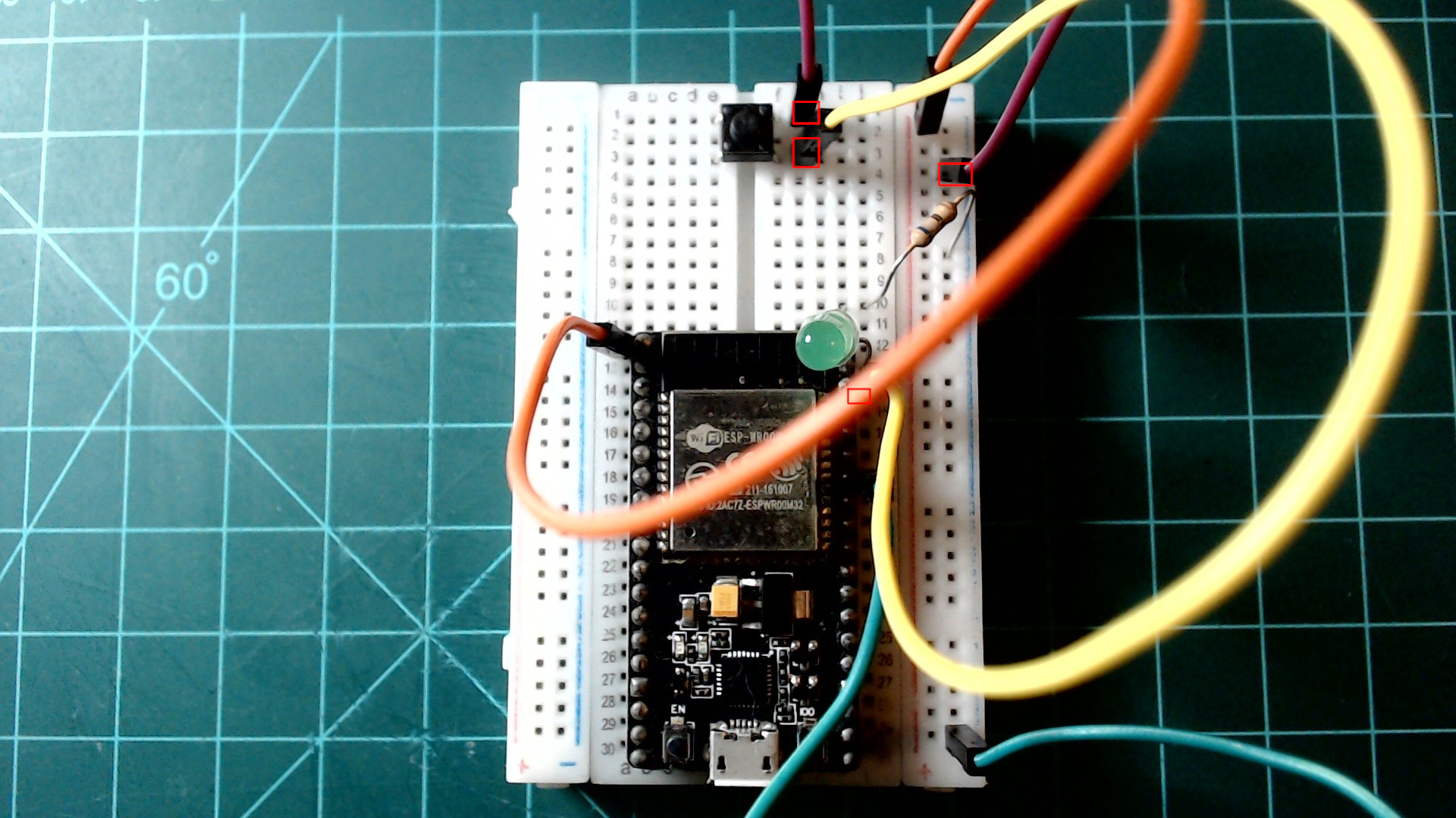
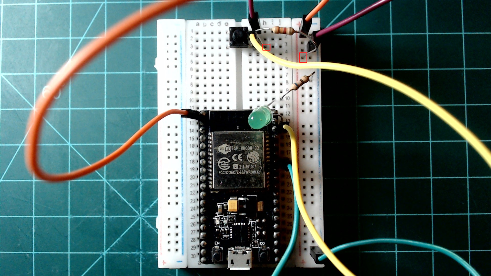
Place your button so that it is near the end of your breadboard and bridges the gap between the two halves. Also, connect a wire from any of the pins labeled “3V3” on the NodeMCU to the other rail next to the ground rail. This rail will now be powered with 3.3 volts.
6mm push buttons fit perfectly across the gap in the center of the breadboard.
 |
Connect one side of the button to GPIO22 and the other side of the button to the ground rail. These connections allow for the pin to be set to 3.3V when the button is pressed, otherwise the pin will be at 0 volts… right?
This setup is missing an important component. We will learn what it is when we run the program.
 |
Plug in the NodeMCU and acquire a REPL in the shell tab. Then edit and save a main.py file to the NodeMCU (overwriting the previous one) that contains the code below. After it is saved, press the reset button on the NodeMCU to run your new program.
from machine import Pin
from time import sleep_ms

button = Pin(22, Pin.IN)

while(True):
    print(button.value())
    sleep_ms(100)
You will see that this program continuously prints the value of the button pin (GPIO22) to the REPL. This is resembled as either a “1” or a “0” with a “1” indicating that the pin is high (3.3V), and a “0” indicating that the pin is low (0V or ground).
Try pressing the button. You will notice that the output is not what is expected. This is because the circuit is missing a critical component called a “pull-up resistor”. This will be added next.
External Pull-Up Resistor
Previously, the circuit did not give the desired output because GPIO22 is never set directly to 3.3V when the button is not pressed. A pin in this state is referred to as “floating” because it is floating somewhere between 0V and 3.3V. To fix this, a high value resistor can be used to connect the pin directly to 3.3V.
Unplug your NodeMCU. Then, use a resistor in the range of 1kΩ - 10kΩ to connect the side of the button that is connected to GPIO22 to the 3.3V rail as shown in the image below.
The pull-up resistor sets the pin to 3.3V when the button is not pressed.
 |
Plug in your NodeMCU and acquire a REPL. Press the reset button to run the same program on the NodeMCU as before. Observe the REPL. You should now see that that the REPL is continuously outputting 1’s. If you press the button, you should see that the output changes to 0’s.
Internal Pull-Up Resistor
There is another way to implement a pull-up resistor. The ESP32 microcontroller contains pull-up resistors that can be enabled through your program.
Remove the pull-up resistor that you just added from your breadboard. Then, edit your main.py script to be the code below.
from machine import Pin
from time import sleep_ms

button = Pin(22, Pin.IN, Pin.PULL_UP)

while(True):
    print(button.value())
    sleep_ms(100)
You should see that your program displays the same output and behavior as with the external pull-up resistor.
Putting it All Together
Now take everything you have learned in this section to write and upload a program to your NodeMCU that turns on the LED whenever the button is pressed. Do not change the components on the breadboard while you do this. Good luck!
Click here to view a solution.
from machine import Pin
from time import sleep_ms

led = Pin(23, Pin.OUT)
button = Pin(22, Pin.IN, Pin.PULL_UP)

while(True):
    if not button.value():
        led.value(1)
    else:
        led.value(0)
Conclusion
Now that you have completed this guide, you should be familiar with the basics of programming GPIO pins on an ESP32 NodeMCU with MicroPython. I encourage you to try experimenting with writing your own programs.
Next guide: Timers and Interrupts with an ESP32 NodeMCU and MicroPython
1
ESP32-WROOM-32 on Amazon Link