In the previous guide about GPIO input and output, an infinite loop had to be run in order to continuously check for a button press or to blink the led at a defined interval. Timers and interrupts are a more efficient methods of doing those same tasks.
Prerequisite Guides
Supplemental Guides
You Will Need
| ESP32 NodeMCU |
| MicroUSB Cable |
| Computer running Windows, Linux, or MacOSX |
| Breadboard |
| LED |
| 46Ω - 100Ω Resistor |
| 6mm Push Button |
| Jumper Wires |
Setup
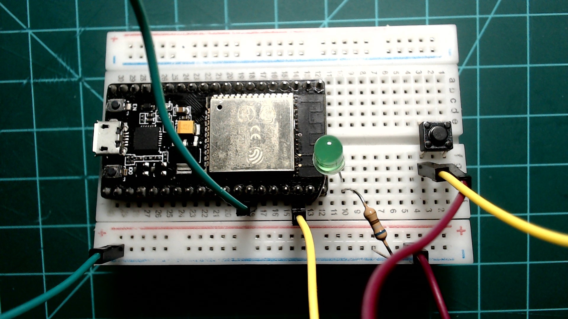
This guide assumes that the breadboard is already populated with the components from the previous guide (a LED and resistor connected in series to GPIO23 and a button connected to GPIO22). Also remember to connect one of the ground (GND) pins on the NodeMCU to the ground rail on the breadboard.
An LED connected to GPIO23 and a button connected to GPIO22. The button should have a pull up resistor specified in the pin declaration.
 |
Timers
Timers are useful when code needs to be executed at a specific interval, such as blinking an LED. Instead of programming delays inside of an infinite loop, a periodic timer with a callback can achieve the same outcome while also allowing other processes to run.
Initialization
The code below is an example of a timer initialization. This timer would print “timer callback” every 1000 milliseconds.
timer = Timer(period=1000, mode=Timer.PERIODIC, callback=lambda t:print("timer callback"))
Each of the parameters is explained below:
- The first parameter is the period in milliseconds. This is the amount of time until the callback is run.
- The second parameter is the mode. This can either be
Timer.PERIODIC or Timer.ONE_SHOT (these will be explained next).
- The third parameter is the callback. This is the function (or lambda) that will be called every period of the timer.
Periodic Timer
A timer in periodic mode means that the callback function is continuously called every period.
The following code has the same outcome as the blinking LED in the previous guide, however now it is implemented with a periodic timer. Copy the code into your editor and upload the file to your NodeMCU as “main.py” to test it for yourself.
from machine import Pin, Timer

led = Pin(23, Pin.OUT)
led.value(0)

timer = Timer(0)
timer.init(period=1000, mode=Timer.PERIODIC, callback=lambda t:led.value(not led.value()))
Notice that when you run this code with the NodeMCU connected to your computer and Thonny open, that you still have a REPL prompt >>>.
You can test one shot mode by replacing Timer.PERIODIC in the initialization statement to Timer.ONE_SHOT. The only difference will be that the LED only toggles once before stopping.
Interrupts
Interrupts are useful for when code needs to be run in response to an event, such as a button press. Instead of continuously checking the state of a button through the use of an if statement within a while loop, an interrupt request (IRQ) can be attached to a button pin to run an interrupt service routine (ISR). This achieves a more efficient and more effective program.
Below is an example of attaching an IRQ to a GPIO pin.
button.irq(trigger=Pin.IRQ_RISING, handler=lambda t:led.value(not led.value()))
Each of the parameters is explained below:
- The first parameter is the trigger. This is the event that will trigger the handler (ISR) to run. This can be either
Pin.IRQ_FALLING, Pin.IRQ_RISING, or both (Pin.IRQ_FALLING | Pin.IRQ_RISING). These will be explained next.
- The second parameter is the handler. This the function (or lambda) that will be run when the trigger event happens.
Signal Edges
When the button connected to GPIO4 is pressed it generates a signal resembling the image below. The high voltage in our case is 3.3V and the low voltage is 0V.
An example of a signal generated by a button press.
 |
As you can see, a falling edge lines up to when the button is pressed, and a rising edge lines up to when the button is released.
Falling Edge
The following code attaches an IRQ to the button pin, GPIO4. This IRQ looks for a falling edge. In our case, this is a button press. When the falling edge is detected the handler will be triggered. The handler below is a lambda function that toggles the LED. Copy the code into your editor and upload the file to your NodeMCU as “main.py” to test it for yourself.
from machine import Pin

led = Pin(23, Pin.OUT)

button = Pin(22, Pin.IN, Pin.PULL_UP)
button.irq(trigger=Pin.IRQ_FALLING, handler=lambda t:led.value(not led.value()))
When testing this code you may notice that it does not seem to behave consistently when tested. This is due to the button bouncing when pressed. We will fix this in the next section.
You can get the LED to toggle on a button release by simply changing the trigger from Pin.IRQ_FALLING to Pin.IRQ_RISING. You can also get it to toggle in response to both events through the use of a bitwise “or” operator: Pin.IRQ_FALLING | Pin.IRQ_RISING.
Debouncing
No button makes perfect contact in an instant when pressed. Instead it may bounce from low to high a few times before finally resting at its final position. Below is an example of a button press signal with bounce.
An example of a button press signal with bounce.
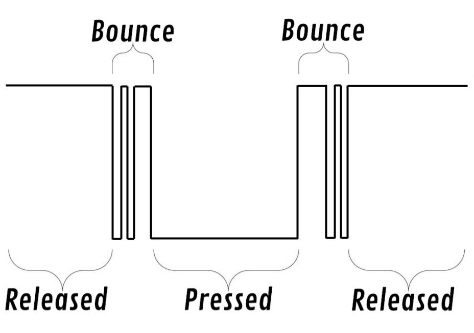 |
You’ll notice that near the falling edge and near rising edge the signal bounces quickly between low and high. This was the source of the inconsistency from the previous example. Luckily this can be fixed with relative ease.
To fix this through code we can simply check consecutive sample readings of the button. If a desired threshold of consistent consecutive button samples is met, we can use it as a true button press, otherwise it will be determined to be the button bouncing and subsequently ignored.
Below is modified code to toggle an LED on a falling edge. To debounce the button we created a function called “debounce” which checks consecutive signal reads. In our case we are using 32 samples to check for consistency. When used, this function will ensure that we only run the rest of the ISR code when a “true” falling edge is detected. Copy the code into your editor and upload the file to your NodeMCU as “main.py” to test it for yourself. Note that we also changed the handler from a lambda to a normal function.
from machine import Pin

led = Pin(23, Pin.OUT)
button = Pin(22, Pin.IN, Pin.PULL_UP)

def debounce(pin):
    prev = None
    for _ in range(32):
        current_value = pin.value()
        if prev != None and prev != current_value:
            return None
        prev = current_value
    return prev


def button_callback(pin):
    d = debounce(pin)

    if d == None:
        return
    elif not d:
        led.value(not led.value())

button.irq(trigger=Pin.IRQ_FALLING, handler=button_callback)
You should observe that the LED is now reacting much more consistently to the button press. Feel free to fiddle with the number of debounce samples. 32 is just an arbitrary value that we found worked well for us.
Putting it All Together
You have now learned how to use timers, interrupts, and how to debounce a button signal through code. Leave the components on the breadboard as is and try one last exercise on your own. Use everything you have learned in this guide to write a program that does the following:
- When the button is pressed, toggle the LED once every second.
- When the button is released, stop blinking the LED.
- Use an interrupt and timer to achieve this, do not use an infinite while loop.
Hints:
- Remember that an IRQ trigger can be set to a rising and falling edge by using a bitwise “or” operator:
Pin.IRQ_FALLING | Pin.IRQ_RISING
- A timer can be stopped by using
timer.deinit().
Below is a gif demonstrating the program. Good luck!
Demonstration of the final exercise.
 |
Click here to view a solution.
from machine import Pin, Timer

led = Pin(23, Pin.OUT)
button = Pin(22, Pin.IN, Pin.PULL_UP)

def debounce(pin):
    prev = None
    for _ in range(32):
        current_value = pin.value()
        if prev != None and prev != current_value:
            return None
        prev = current_value
    return prev

timer = Timer(0)

def button_callback(pin):
    d = debounce(pin)

    if d == None:
        return
    elif not d:
        timer.init(period=1000, mode=Timer.PERIODIC, callback=lambda t:led.value(not led.value()))
    else:
        timer.deinit()


button.irq(trigger=Pin.IRQ_FALLING | Pin.IRQ_RISING, handler=button_callback)
Stay tuned for more NodeMCU guides!