Used in This Guide
| Breadboard |
| Breadboard Power Supply |
| PIR Sensor Module |
| IRFZ44N MOSFET |
| Yellow LED |
| 330Ω Resistor |
| Jumper Wires |
| Sacrificial USB Cable |
| 2 Two Pin Screw Terminal Blocks |
| 4 Ferrule Terminals |
| Ferrule Crimper |
| Protoboard |
| Soldering Iron |
| Solder |
The Problem
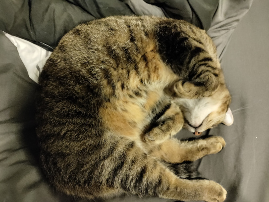
I live with a cat that prefers to have his drinking water moving (otherwise he will move it himself by hitting the bowl with his paw which causes spillage). To solve this, I got him a fountain that uses a water pump to keep the water moving. Due to my current living situation, I need to keep the fountain in my bedroom. The problem is that I can’t stand the sound of trickling water. I find it very annoying, and I have found that it tends to worsen my mood.
Sven, my cat.
 |
My Solution
Mount a motion sensor module to the fountain to detect if a cat is near. If a cat is detected, supply power to the fountain for a set period of time before turning off. This will limit the fountain to being on only when a cat is nearby.
Components
The core components of this project are a PIR sensor and a MOSFET. I’ll briefly explain how these fit into this project and provide some external sources for more information.
PIR Sensor
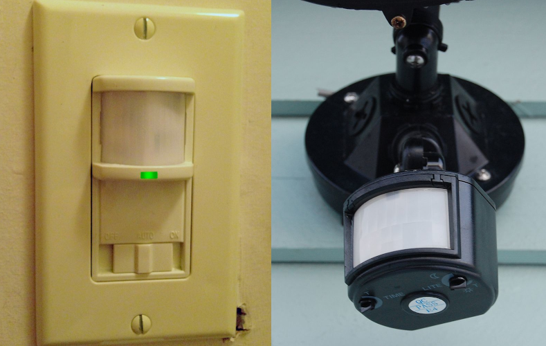
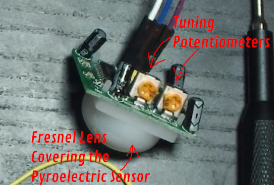
The PIR (passive infrared) sensor uses a pyroelectric sensor covered by a fresnel lense to detect changes in heat (infrared light) around the sensor. When a change is detected, the sensor outputs a high signal for a set duration, then, it changes back to outputting a low signal until it is triggered again. There sensors are commonly used for security systems and automatic lighting.
Some applications for PIR sensors.[1]
 |
These sensor modules often come with two potentiometers that allow for the sensor to be tuned. One of the potentiometers sets how long the sensor will output a high signal when triggered. The other potentiometer sets the sensitivity of the sensor to being triggered.
Some applications for PIR sensors.
 |
My particular module does not have this, but often these sensor modules will have a jumper that can be used to set the mode of the sensor to “reapatable” or “non-repeatable”. A sensor in non-repeatable mode will turn off after it’s high duration is up and then wait to detect another change before triggering again. A sensor in “repeatable” mode will keep the output high after the duration time is up as long as it still detects the heat source.
If you want to learn more about how PIR sensors work, watch this video.
MOSFET
MOSFETs (metal-oxide-semiconductor field-effect transistors) are more capable of handling higher current loads that their BJT (bipolar junction transistor) counterparts. Applying a voltage to their “gate” pin allows for current to flow between their “drain” and “source” pins.
Some applications for PIR sensors.
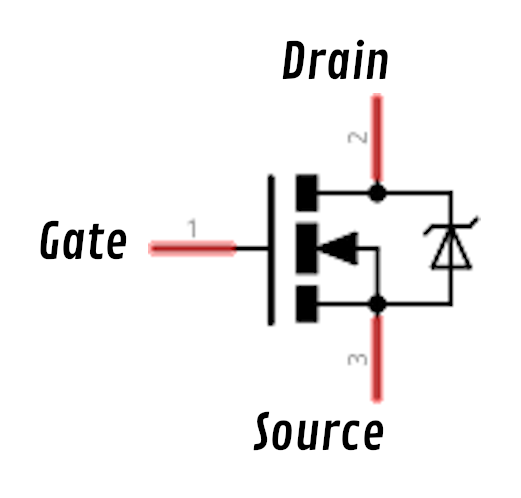 |
For my application, I will use a IRFZ44N N-Channel MOSFET to switch on my water fountain when the PIR sensor outputs a high signal.
This video provides a good breakdown of applications for different kinds of transistors, including MOSFETs.
Assembling the Test Circuit
The first circuit that I assembled was a simple circuit that lights up an LED when a PIR motion sensor is triggered.
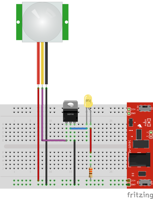
I like to use a breadboard power supplies when prototyping projects like these on a breadboard. They fit perfectly into the power rails on both sides of the breadboard and you can power them either through usb or by providing 7-12V through the barrel jack. They can also be set to provide either 3V3 or 5V. I started off by plugging my breadboard power supply into the breadboard and setting it to 5V. Then, I plugged the PIR sensor module, MOSFET, LED, and 330Ω resistor into the breadboard and made connections according the image below.
The PIR sensor test circuit.
 |
When powered, this circuit resulted in the LED lighting up for a set duration when the PIR sensor was triggered, as shown in the gif below. I used a screwdriver to adjust the sensitivity and duration potentiometers until the sensor module was sensitive enough to test and the duration was only a couple of seconds.
The test circuit. The LED lights for a duration when the PIR sensor is triggered.
 |
The important part of this circuit is that the LED isn’t being powered directly from the PIR sensor module. It is being powered through the MOSFET which gets a signal to its gate from the PIR sensor module. This distinction is important because it means that we can power high current loads (like water pumps) that would otherwise damage the delicate components like the ones the PIR sensor module.
Adding a USB Cable
Now that we know the PIR sensor works with the test setup we can:
- Remove the breadboard power supply and power the circuit directly through USB power (male connector)
- Add an output USB connection that can be connected to loads that take USB power like my water fountain
First I found an unused USB cable that I could use for this project. I chose a USB extender cable (female USB to male USB connectors), so that I could easily use the motion sensing circuit for any USB powered device. I cut this cable in half, stripped off the outer casing at the ends of the split cables, and stripped the power wires (red and black) for each of the split cables. Then, I crimped ferrule terminals onto each of the four power wires. Ferrule terminals will make better contact than bare wire when attached to screw terminals.
Crimping ferrule connectors to the power wires on both sides of a split USB cable.
 |
Below is a drawing of the new circuit. I used two pin screw terminals for both the input and output so that the power wires from the input and output usb cables can be screwed in.
The PIR sensor circuit with input and output screw terminals.
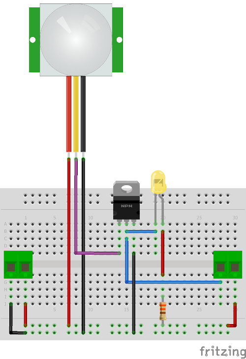 |
After assembling the new circuit on a breadboard, I screwed in the cable with the male usb connector into the input (left side), and the cable with the female usb connector into the output (right side). Then I plugged the male USB connector into a 5V USB power supply and I plugged the female USB connector into the the USB cable connected to the water fountain. Then I positioned the sensor using alligator clips and tested the circuit.
Testing the breadboarded circuit with my water fountain connected to the output.
 |
Each time the fountain is powered it takes a couple of seconds for the pump to start running, but you can see that the LED still turns on immediately when it detects motion in front of it. After the duration passes, it briefly turns off, but then immediately turns on again because my cat moves his head.
Finalizing the Device
To make the motion sensor circuit more sturdy, I soldered it onto protoboard. I also designed and 3D-printed some wall mounts that the protoboarded circuit and PIR sensor module can be attached to.
Attaching the protoboarded circuit to the 3D-printed mounts.
 |
I then mounted the sensor circuit and PIR sensor module on the wall next to the water fountain. I also made sure to test and tune the sensor so that it was sensitive enough to detect when a cat was nearby and stayed on long enough for a cat to see the water moving.
My cat triggering the PIR motion sensor which turns on the water fountain.
 |
Conclusion
I hope that you were able to learn something in this guide, whether it be a component that could be useful to you, or some inspiration on how electronics can be used to improve your own life.
Stay tuned for more guides!
1
Wikimedia Foundation. (2021, October 14). Passive Infrared Sensor. Wikipedia. Retrieved November 27, 2021, from https://en.wikipedia.org/wiki/Passive_infrared_sensor#/media/File:Light_switch_with_passive_infrared_sensor.jpg. Link