This guide will include taking apart an appliance and exposing connections to residential mains voltage which can range from 110V to 240V across the globe. When disassembling an electronic device make sure to be safe by ensuring the device is UNPLUGGED and POWERED OFF.
Prerequisite Guides
Supplemental Guides
Used in This Guide
| Sacrificial Appliance (Space Heater) |
| ESP8266 NodeMCU |
| Breadboard |
| MicroUSB Cable |
| 4 2N2222 Transistors |
| 4 200Ω Resistors |
| Jumper Wires |
| 1 Two Pin JST Connector |
| 1 Four Pin JST Connector |
| Computer running Windows, Linux, or MacOSX |
The Goal
Modify an appliance with button inputs using IOT microcontrollers to function autonomously using external sensors and controls. I will be presenting this guide using a small space heater as an example, however, I hope that this guide is clear enough for readers to following along with their own appliance with similarly functioning button inputs. If you are attempting to use this guide to modify your own appliance, please feel welcome to use the Micronote Community Discord server as a resource.
Heater before being disassembled or modded.
 |
I will be using ESP8266 NodeMCUs in this guide because they are cheaper than ESP32s and I own many of them, but people should be able to follow this guide using ESP32s as well.
Safety
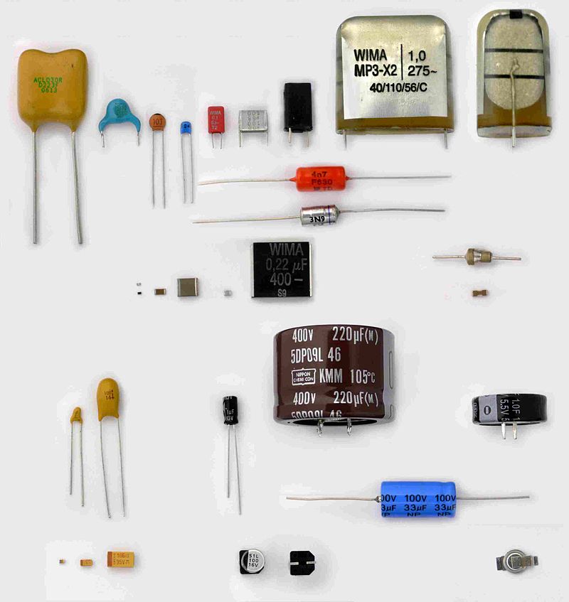
As I point out in the warning at the beginning of this guide, avoid exposing your hands to dangerous mains voltage by making sure that the appliance you are disassembling is unplugged. When opening an appliance that was once plugged in, you must be cautious of high voltage capacitors. They may be holding a charge even after the appliance has been unplugged. You can be safe by testing their voltage as you come across them with a multimeter, and you can be extra safe by also letting the appliance remain unplugged for at least a day in advance of working on it.
Capacitors can hold charge even after a device has been powered off.[1]
 |
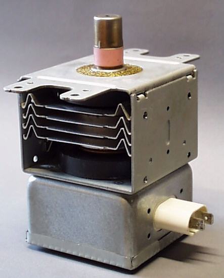
My last general rule of advice is to know what to expect on the inside of your device before opening it. Do some research on the type of appliance you are opening. Make sure that you know what hazards to look out for. Besides high voltages, some devices (notably older ones) can contain dangerous materials that are very harmful if inhaled. An example of one such material is beryllium oxide used in magnetrons for microwaves.
The ceramic insulator used in magnetrons often contains beryllium oxide.[2]
 |
All this being said, do not fear opening up electronic devices. Observing how existing devices function is valuable experience for electronics enthusiasts.
Opening the Device
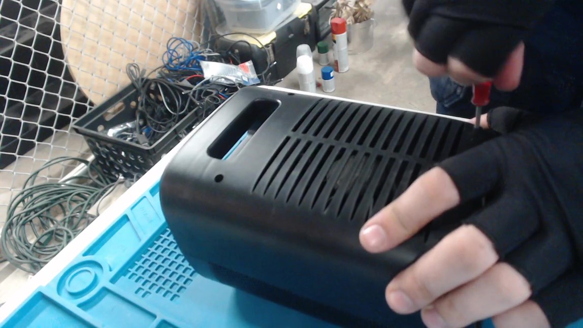
When opening the device take care to be as gentle as possible to keep its parts intact. I also highly recommend taking lots of pictures of the disassembly process, or even video recording yourself as you take apart the device. This will help you later when you want to put the device back together. The space heater had four screws in the back that had to be removed to gain access to the internals of the appliance. I removed these screws with a screwdriver and then removed the back panel of the enclosure. I placed all fasteners on a magnetic pad to make sure that they didn’t get lost.
Unscrewing the back panel of the heater.
 |
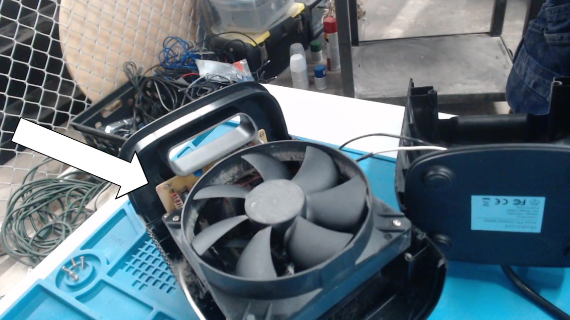
To do the modifications, I needed access to the circuit board with the buttons on it located at the top of the unit. The fan and heating element were blocking access, so I unscrewed and removed them.
Inside of the heater. The circuit board is blocked by the fan and heating element.
 |
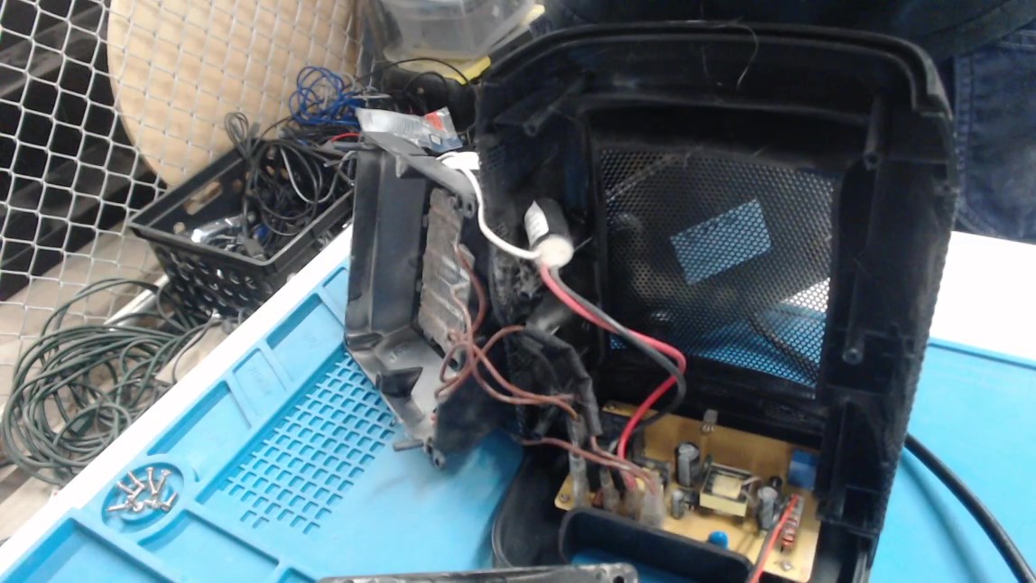
After removing the fan and heating element, I was able to access the the screws fastening the circuit board to the enclosure.
The fan and heating element removed.
 |
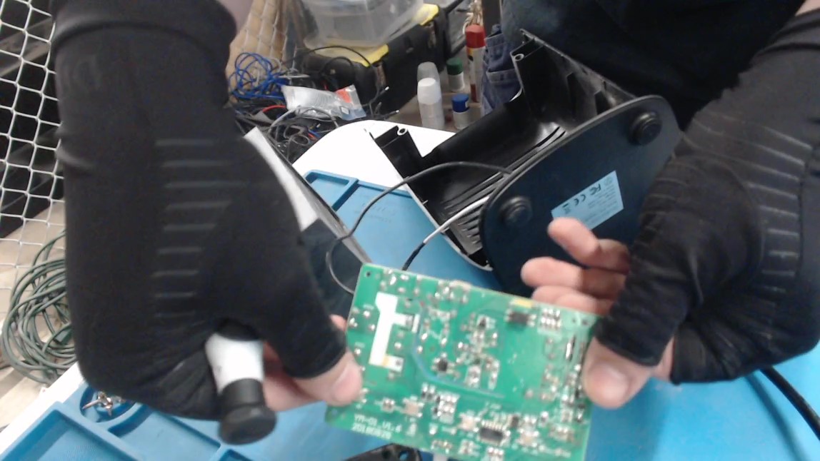
I uncrewed these and removed the circuit board.
The pcb after being removed from the heater.
 |
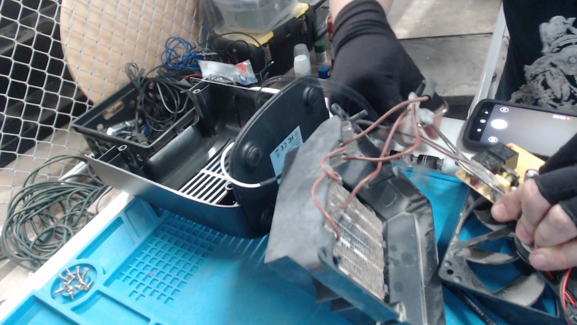
Lastly, I unplugged the wires connecting the pcb to the other components. I recorded which wires were connected to where on the pcb by taking pictures. This made it much easier to reassemble the device later.
Disconnecting the wires from the pcb.
 |
Circuit Board Analysis
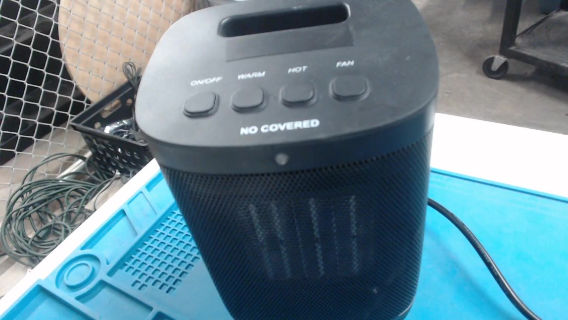
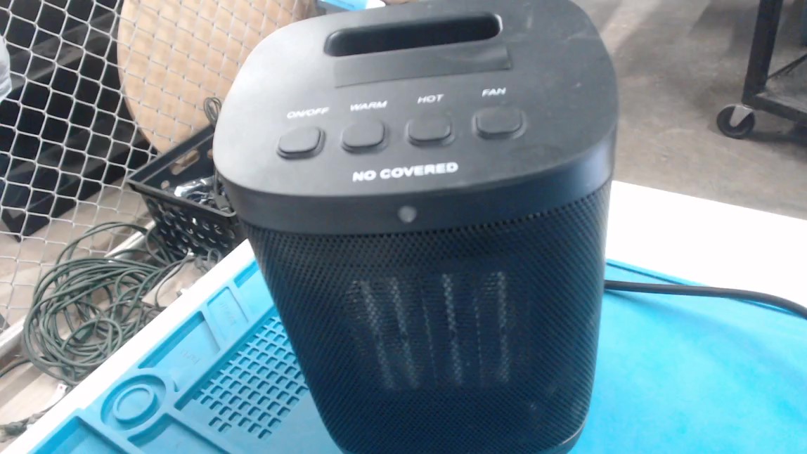
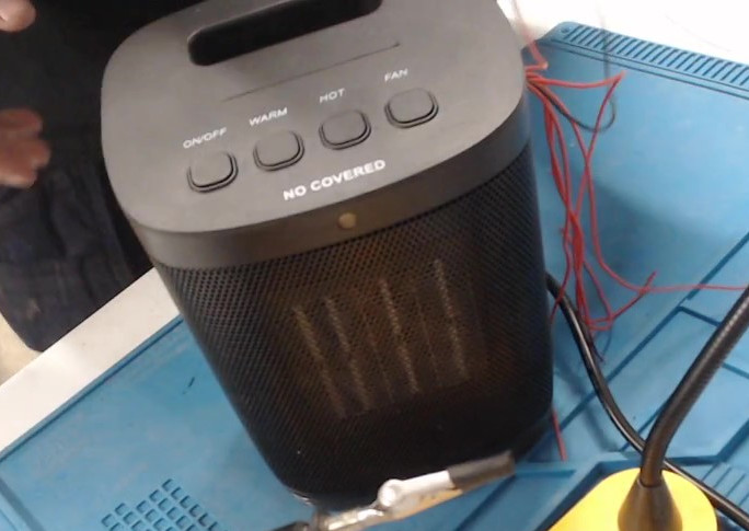
For this mod, I needed to locate the contacts for the input push buttons on the circuit board. On my assembled heater there are four buttons on top of the device labeled: “ON/OFF”, “WARM”, “HOT”, and “FAN”.
The four buttons on top of my space heater.
 |
These plastic buttons on the enclosure line up with the surface mounted buttons on the pcb such that when pressure is applied to the plastic button on the enclosure, the button on the pcb is pressed.
The corresponding surface mounted buttons on the pcb.
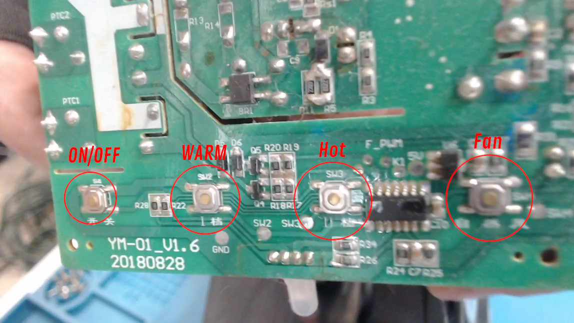 |
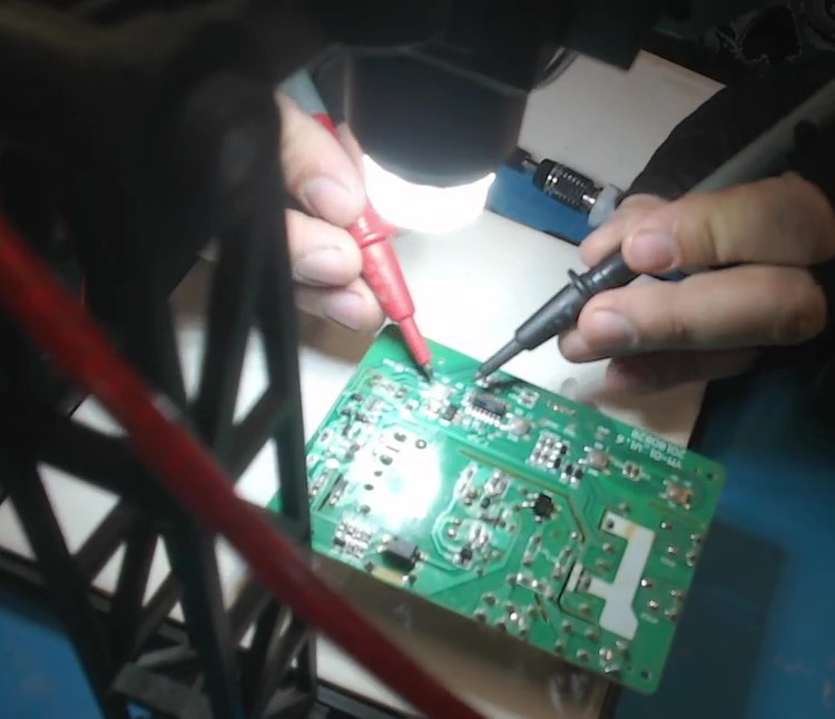
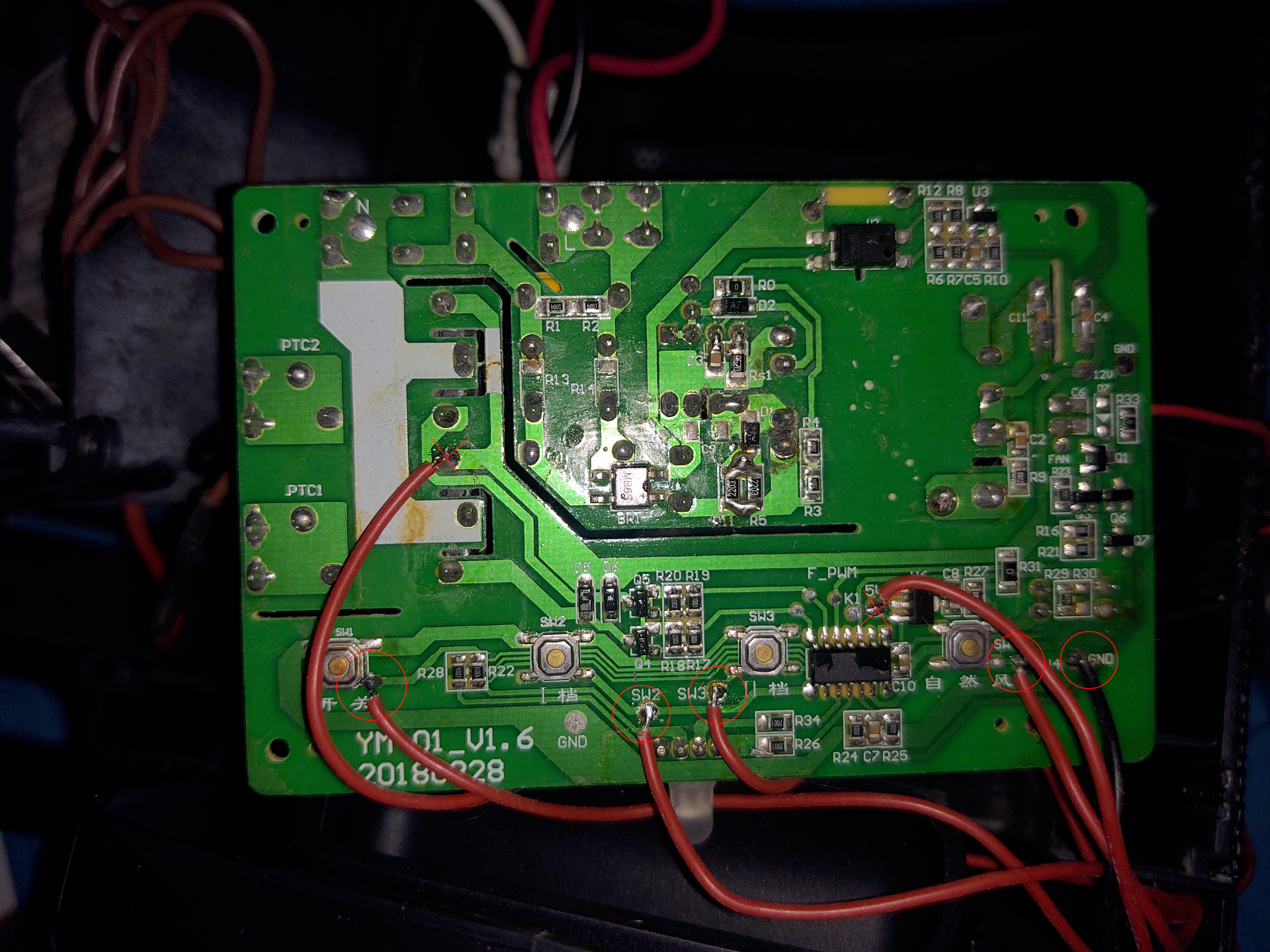
The silkscreen on the pcb labels the buttons from left to right as “SW1”, “SW2”, “SW3”, and “SW4”. I continuity tested the contacts of the buttons and discovered that one side of all of these buttons were all connected to the GND node.
Continuity testing the pcb.
 |
This means that for each button I will need to solder one wire to the opposite (not GND) node, totaling four wires. Then solder a single additional wire to the common GND node for a total of five wires.
Attaching Wires
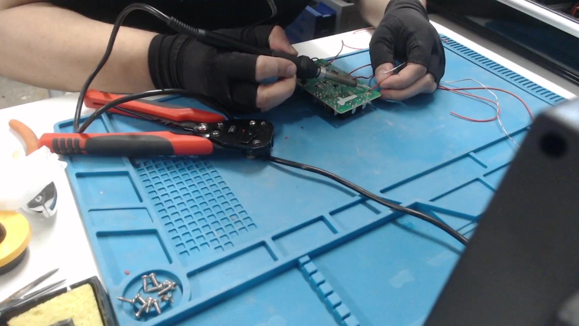
For each button I soldered one red wire to the non-GND connected node. Then I soldered one black wire to the GND node. I recommend using different colored wires for each of the buttons, but I only had red wire at the time, so I used a marker to mark the wires’ insulation near their ends to differentiate them. I also cut these wires long enough to extend out of the device through a hole and into an external breadboard.
Soldering wires to the SW1, SW2, SW3, SW4, and GND nodes on the pcb.
 |
My heater’s pcb conveniently had pads available for the nodes at SW2, SW3, SW4, and GND that I soldered my wires to, but SW1 did not have an extra pad so I soldered the wire on top of one of the non-GND connected button leads. I also soldered two additional red wires: one to the 5V node and one to the unregulated input voltage node. These ended up not being necessary for this mod, and can be ignored when following this guide.
Wires soldered to the pcb. The circled connections are used for the mod, the crossed out connections were unnecessary.
 |
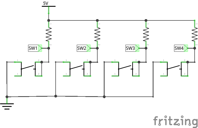
To clarify what I’ve done so far, I drew the schematic below.
Wires soldered to the pcb. The circled connections are used for the mod, the crossed out connections were unnecessary.
 |
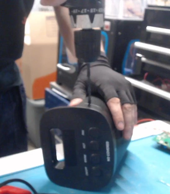
Having access to SW1, SW2, SW3, SW4, and GND nodes through the wires will allow me to complete the mod. To give the wires somewhere to exit the enclosure, I drilled a hole in the plastic casing near the edge of where the PCB is fastened.
Drilling an exit hole for the wires.
 |
Now the heater was ready to be reassembled.
Reassembling the Heater
First I reinstalled the PCB with my wires exiting through the drilled hole. Then, I reinstalled the heating element, making sure to preserve the original pcb connections from the assembled heater. Then, I reinstalled the fan, preserving its connections to the pcb. Lastly, I reinstalled the back enclosure, completing the reassembly.
I reassembled the heater, preserving the original electrical connections.
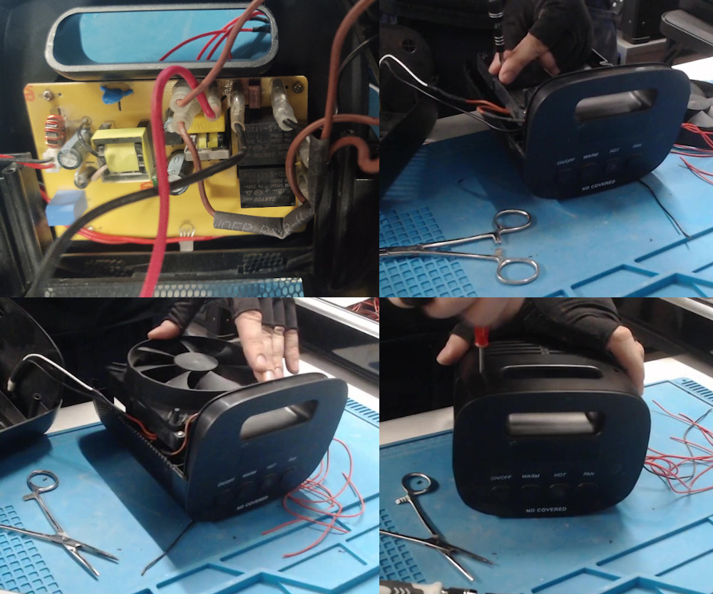 |
After your device is completely reassembled, test it to make sure it is working exactly the same as it was before disassembling it.
The assembled heater with the installed wires.
 |
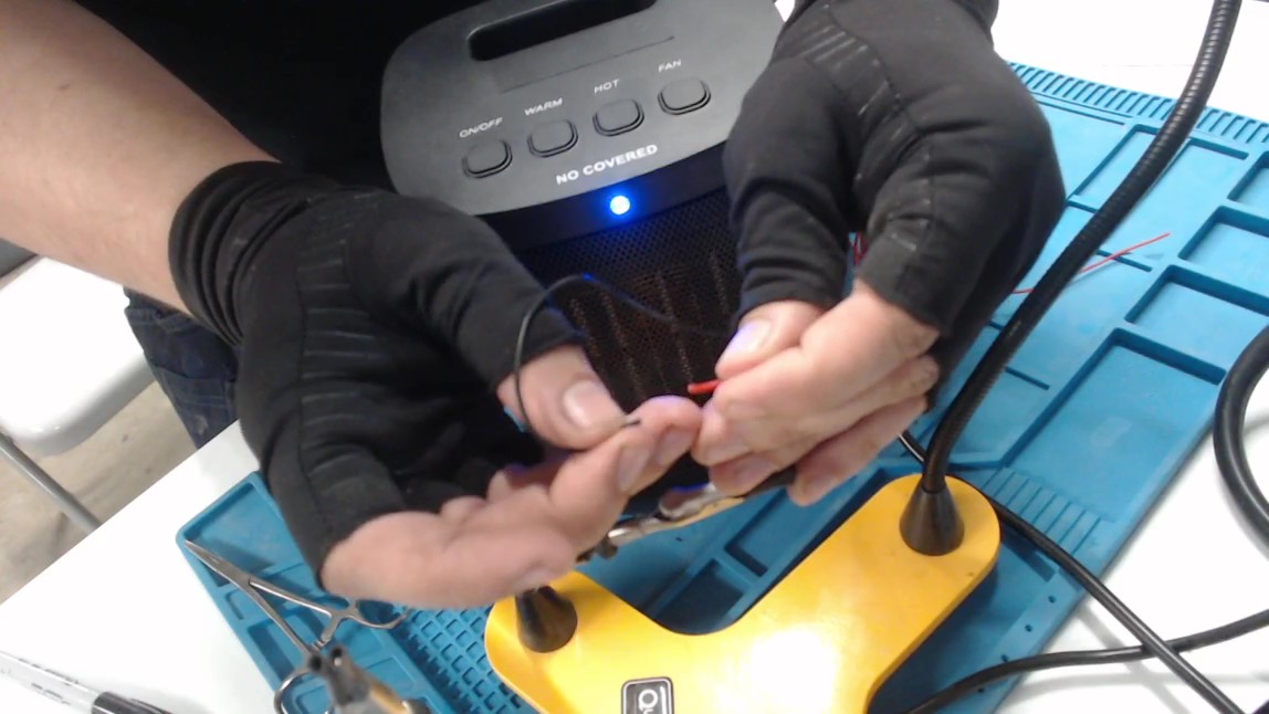
Testing the Wires
If you analyzed the pcb and correctly installed the wires, you should be able to activate the buttons’ functions by tapping the wires for each button to their common connection, in my case GND.
Testing the device's functions by connecting the wires.
 |
I soldered a jst connector onto the four button wires. This is not strictly necessary, but it will allow me to more easily use the wires connected to the button nodes.
Attaching a jst connector to the button wires for ease of use.
 |
With the wires connected to the buttons, the heater was ready to be connected to an ESP8266 microcontroller.
Connecting the Microcontroller
Tapping wires together instead of pressing buttons isn’t much of an improvement over simply pressing the original buttons on the appliance. I want to enhance this heater by allowing button presses to be done autonomously with an external microcontroller. This requires somehow converting an output signal from my microcontroller into a connection between one of the button wires and GND.
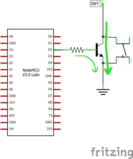
We need a component that can convert an output signal into a connection between node SW1 and GND.
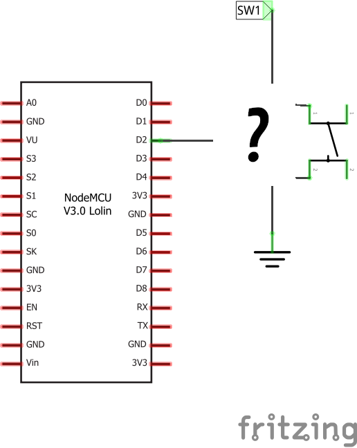 |
An NPN bipolar junction transistor is a good fit for this task. An NPN transistor can function as a switch. When the base of the transistor is powered, it will allow current to flow from the collector and base to the emitter, completing the circuit. A resistor can be put in series with the base to protect the signal source from excess current.
A transistor can be used as a switch, bypassing the physical button in the appliance.
 |
We can use this same circuit for all of the button wires to create transistor switches that can control each function of the heater using an output signals from microcontroller pins.
Each button wire (SW1, SW2, SW3, SW4) connected to a microcontroller pin using an NPN transistor.
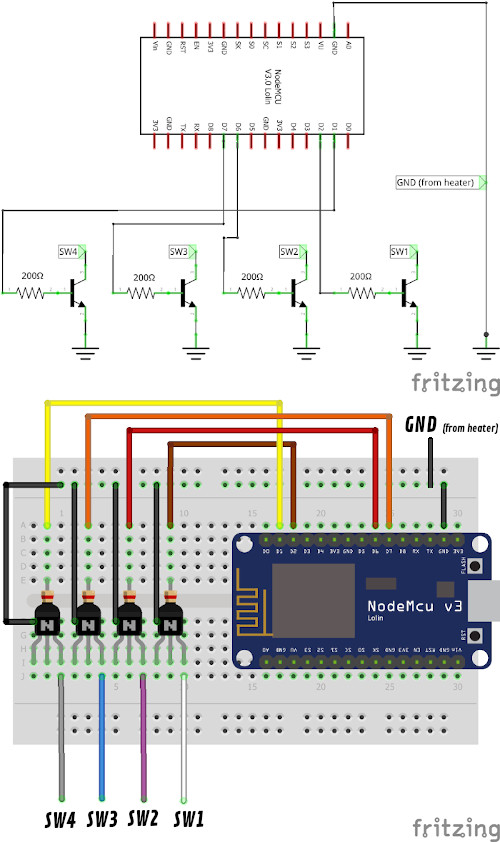 |
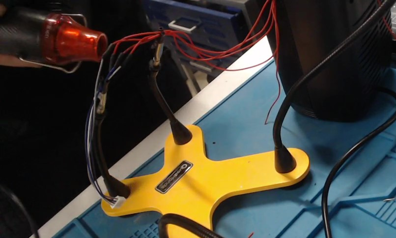
I assembled this setup on a breadboard using four 2N2222 NPN transistors and four 200Ω resistors. I used a ESP8266 NodeMCU as my microcontroller and connected the base from all four transistors to different I/O pins.
Breadboard setup with transistors.
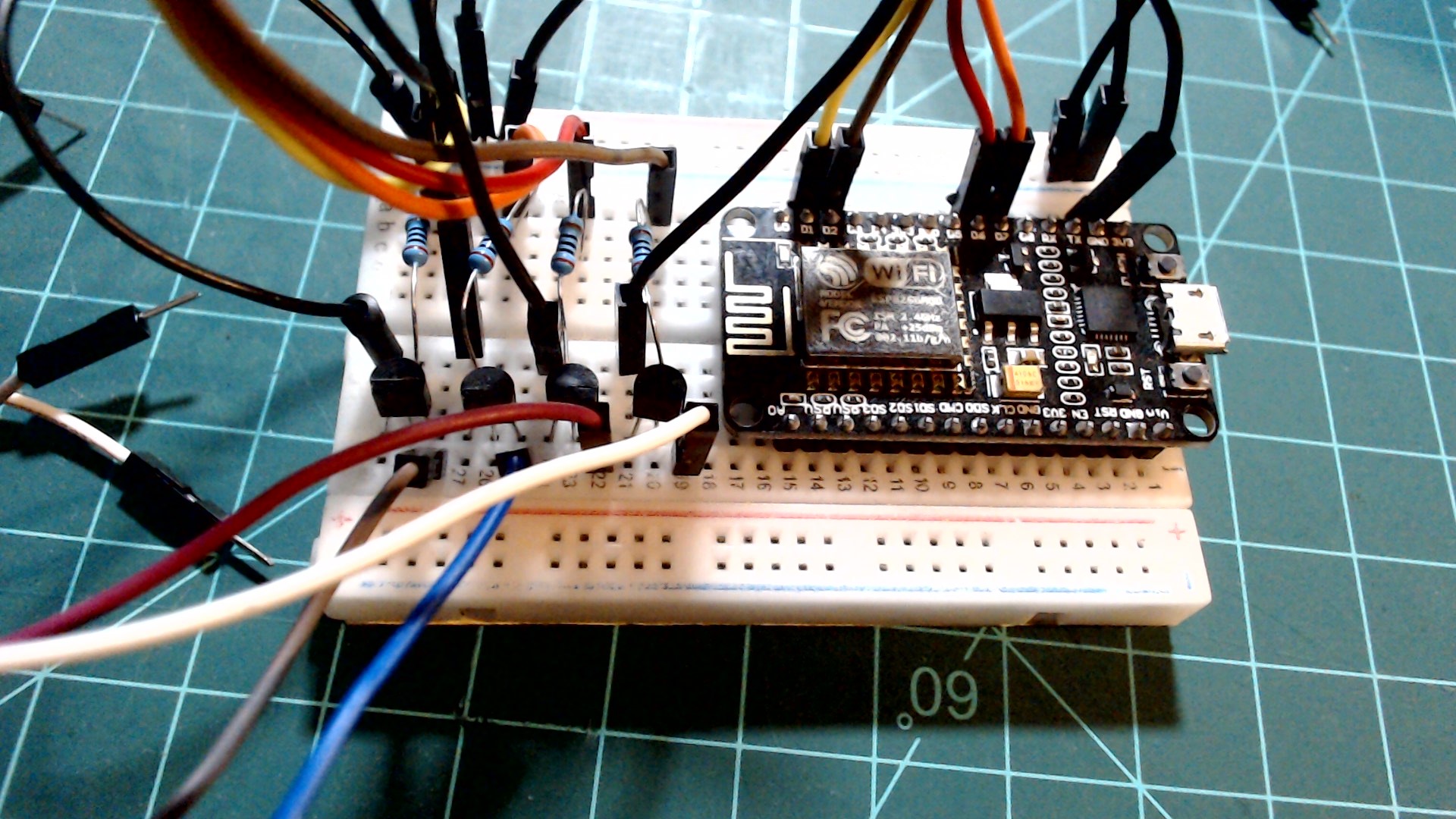 |
Then I connected the ground wire from the heater to a GND pin on the NodeMCU and the collector of each transistor to its paired button wire from the heater. I also plugged in the heater at this point.
Now the microcontroller and heater is ready to be programmed.
Programming the Heater
I wrote this program in MicroPython using the Thonny IDE. First, I added the following imports.
from machine import Pin
from time import sleep_ms
Each of the heater buttons are connected to the microcontroller through an NPN transistor. The “ON/OFF” button is connected through the SW4 wire to NodeMCU pin D2 (GPIO4), the “WARM” button is connected through the SW3 wire to D6 (GPIO12), the “HOT” button is connected through the SW2 wire to D7 (GPIO13), and the “FAN” button is connected through the SW1 wire to D1 (GPIO5). I’ll declare a Pin object for each of these pins and set them as outputs.
power_button = Pin(4, Pin.OUT)
warm_button = Pin(12, Pin.OUT)
hot_button = Pin(13, Pin.OUT)
fan_button = Pin(5, Pin.OUT)
Next, I created a function called simulate_button_press that takes in a Pin object and quickly toggles it on and off using a delay (as if it has been pressed).
def simulate_button_press(button_pin):
    button_pin.value(1)
    sleep_ms(5) # small delay to simulate button press
    button_pin.value(0)
Below is the full Python script.
from machine import Pin
from time import sleep_ms

power_button = Pin(4, Pin.OUT)
warm_button = Pin(12, Pin.OUT)
hot_button = Pin(13, Pin.OUT)
fan_button = Pin(5, Pin.OUT)

def simulate_button_press(button_pin):
    button_pin.value(1)
    sleep_ms(10) # small delay to simulate button press
    button_pin.value(0)
At this point I plugged my ESP8266 NodeMCU into my computer using a microUSB cable. Then I set the interpreter to be “MicroPython (ESP8266)” and set the port to the port of my NodeMCU (COM3 for me). Then I saved the script to my NodeMCU as “main.py” and pressed the reset button on the NodeMCU.
With the program running on the NodeMCU and plugged into my computer, I can use the REPL in Thonny to access all of the variables and functions that I defined. I can call the simulate_button_press function to activate any one of the buttons.
First, I can turn it on using the following command:
>>> simulate_button_press(power_button)
The heater turns on and automatically enters “WARM” mode as indicated by the blue light. It can now be switched to “HOT” mode using the following command:
>>> simulate_button_press(hot_button)
It can be switched to “FAN” mode using the following command:
>>> simulate_button_press(fan_button)
It can be switched back to “WARM” mode using the following command:
>>> simulate_button_press(warm_button)
Lastly, it can switched off by activating the power button again:
>>> simulate_button_press(power_button)
Conclusion
This is a good stopping point for part 1 of this guide. To summarize, we opened up an appliance, located and soldered wires to the buttons and relevant nodes, set up the breadboard with NPN transistors, and wrote a simple program to simulate button presses on the appliance. Now that the appliance can be accessed by an IOT microcontroller, the appliance is opened up to endless improvements and modifications. I intend to explore some these possibilities later in this series of guides. I hope you are able to follow along with your own appliance. If you need help, feel free to post a message in the Micronote Community Discord server.
Stay tuned for more NodeMCU guides!
1
Benutzer, F. R. (2021, June 10). Capacitor types. Wikipedia. https://en.wikipedia.org/wiki/Capacitor_types#/media/File:Verschiedene_Kondensatoren_2.JPG. Link
2
Wikimedia Foundation. (2021, May 24). Cavity magnetron. Wikipedia. https://en.wikipedia.org/wiki/Cavity_magnetron#/media/File:Magnetron1.jpg. Link